Wednesday, October 22, 2008

The speedometer.

Now, it's time to discuss the instrument console. Due to automotive regulations, every motorcycle needs a back lit speedometer. I wanted a complete speedometer meter kit which included a pickup mechanism. Although there were several analog meter kits I could have used, I thought a digital look would be best for the BugE.

So, browsing the web, I found a complete meter kit at dynotunenitrus.com. It included the meter and also the pickup mechanism. Originally, I ordered the simple XR-SA meter on the left that had a speedometer, odometer & some bonus indicator lights. It was simple and probably would have done the job just fine. For a battery volt meter, I figured I would use the analog meter for now and then switch to a nicer looking bar graph unit at a later time.

When my meter arrived, for whatever reason, I got the nicer rx-srn meter shipped to me instead of the lower cost meter! It's a really nice looking meter. However, it has an extra feature I didn't need - a fuel gauge on the left side of the display!

It seemed too bad to install a retro looking charge meter from EV parts when I now had such a fine looking bar graph included in the digital unit. Surely, I thought, there must be a way of calibrating that slick looking gasoline bar graph so it would show battery charge instead. Unfortunately, such meters work in totally different ways so I would need a conversion circuit.


So, basically, I need to build or find a circuit that can convert a voltage range from a low charge state of say 45v* to a high charge state of 49V* to be a current flow which would mimic a sender unit current flow for the E-F gauge. This is a tricky circuit for me so I've decided to stick with a temporarily mounted analog gauge for now. Later, when the BugE is on the road, I'll be returning to this feature.
(*Voltage levels may be different)

Other than the unused fuel gauge, it is overall a fine looking speedometer kit. It has wires to allow connection to indicator lights such as brake, hi-beam & turn signals too. It comes complete with a magnetic pickup and even little button magnets to put in the wheels! The meter is programmable and the instructions show show how to set the meter for non-standard wheel sizes if needed. It also comes with a mounting arrangement that allows handlebar or dashboard mounting. (I'll be trying the handlebar mount first)

The speedometer also has some indicator lights can monitor what the real lights should be doing. I'll be using a multi-pin Molex connector on the wire bundle so the speedometer wiring can be quickly detached from the cowl wiring should the cowl need to be removed from the chassis for servicing.

Monday, October 13, 2008

Mirrors, headlights & front storage area door.

Since the cowl is not mounted to the bug yet, this is a good time to do some little things that will be harder to do once it is mounted to the pivot tube.

The biggest cosmetic change to the 12v system of the BugE is the addition of lighted mirrors. I found some really nice looking EuroSport side mirrors from AutoAnyting.com for arund $18 ea. This model is adjustable so it can be used on either the right or left side. In the photos I've seen on other BugE cars, the mirrors appear to be placed parallel to the lip of the cowl and line up about where the console begins. Since these mirrors are lighted, they have been placed forward about an inch so power wires can pass from them.

As you can see, the mirrors came with spare bulbs and some sheet metal screws. However, I've decided to use some small machine screws instead so the fiber glass is not stressed out as much. When I need to replace the bulbs, this photo reminder will hopefully remind me to press in the two catches on the right side rather than trying to pry off the front. Since the mirrors look so much like they are integrated into the bug, I'm going to try to use the lighted mirrors as primary turn signals. If the lights don't seem bright enough or they don't pass inspection, then I'll be using the small Targa lights that came with the BlueSky kit in the front too.

POST CONSTRUCTION OBSERVATION: February 14, 2009 - Found the Eurosport mirror turn indicators LOOK nice from the front. However, the mirrors need to be angled up since the body mount point is too low. Even when this is done, visibility is rather restrictive. I have replaced the Eurosport mirrors with Izuzu pickup truck mirrors. I also installed a separate DOT approved turn signal pair since the new mirrors do not have turn signal lamps built into them.

Now, it's time to attach the storage door to the body. Originally, I bought some cabinet hinges to do that. However, I could not make them work for me. So, rather than making a special trip to the hardware store just for a pair of hinges, I decided to make my own offset hinge assembly.


Upper-Left shows the materials. Some washers that fit #8 screws, (4) 8-32 - 1/2" screws (note: 8-32 1/2" screws should be flat head white 8-32 screws but I used zinc round head because that's what I had on hand at the moment), (8) 8-32 nuts, (2) two inch gate hinges, some counter edging (used about 8" of it) and some stubby flat-head self-tapping screws with big threads.

Top-Middle The next step was making some notches in the BugE door lip. For marking, I used a hinge as a guide, a pencil to mark and a dremil for cutting.

Top-Left Using a Dremil, I removed about an 1/8" of material from one end of the door so it could go over the hinges when opened.

Middle-Left Where to put the holes? Door holes were based on holes in the hinges. Image shows screws drilled through cover and attached with nuts inside. The inside nuts not only secure the screws, but also serve as spacers.

Middle-Middle Image shows hinges being put on. Note, spacer nuts are left on.

Middle-right Image shows securing nuts attached to top of hinge.

Lower-left Fiberglass material is removed using a dremil in the approximate size and the thickness of each hinge.

Lower-middle An 8" piece of counter edging is attached to the hinges with some stubby flat head self-tapping screws. The screw heads mount to the edging such that no screw head is visible.

Lower-right The door is temporally taped shut to the body with masking tape. Then, from inside, the hinge assembly is attached to the door frame. Note, on the Dremil bit, there is a small home made brass collar on it. This is to prevent the drill from going too far and boring out through the walls of the BugE! After holes are drilled, more stubby screws come to the rescue to secure the assembly to the frame of the door. However, the stubby screws are slightly longer than the BugE wall is thick. So, some washers are used as spacers so they don't need to be fully screwed in. (see circled yellow areas)

While inside the storage area drilling holes, I also marked the location of where the door catch mechanism should go. Once I finished mounting the hinge, I opened the door, drilled a small starter hole from inside to out. Then drilled a hole using a 1" hole saw from outside to in. Then added the included tang and the door is done!


The end result?


Nice. (Well, at least I think so)


Parts used (see materials list above)
Tools - Drill (with drill bit kit), 1" hole saw, Dremil (with cutting bit & drill bit) , Shop light, respirator (for fine fiberglass particles), safety glasses, screw driver, adjustable wrench, pencil, marker, metal ruler, wood vice.
Time used - about 8 hours working casually, 4 hours blogging about it.

Lots of assembly time (maybe too much) is spent thinking about how best to record what I'm doing in digital format. Straight assembly should go much faster - especially if the correct parts are used. I'm sure next time I go to the hardware store, I'll see some cabinet hinges that would have been PERFECT to use instead of doing it the roundabout way I just did! Hey, but that's what this project is about. LEARNING!


To do (related tasks):
  • Hot-glue some new weatherstrip around the door since I wrecked the stripping that was originally on the door.
  • Replace the shiny roundhead screws visible on the outside of the door with white flathead countersunk screws.

Wednesday, October 1, 2008

Wiring the 48V motor.

Since adding a reversing switch is a common option, BlueSky provided some supplemental instructions to do this. To mount the reversing switch properly, the instructions recommended jumping ahead to mount the rear fender, seat and battery tray so the switch could pass through the rear fender properly. Now that those steps are done, it's time to go back to the 48V wiring step. The way I would have liked to assemble would have been to purchase pre-made wires and just install them as per the user manual. However, since no wire kits specific to the BugE were available at that time, it's time to do it the hard expensive way.

For the 48V wires, I decided to construct my own battery cables out of a coil of #4 wire. The cables are stranded so they bend very easily. For cutting the wire, bolt cutters work nice. For stripping, I use a razor knife. For putting on ends, I use a hammer crimper that crimps by being hot with a sledge hammer or in my case an axe. Then I wrapped the ends of the wire in electric tape, put some plastic split tubing on it to protect it, then bolted them. Just to make things difficult, two lug sizes need to be used depending on where the cables attach.

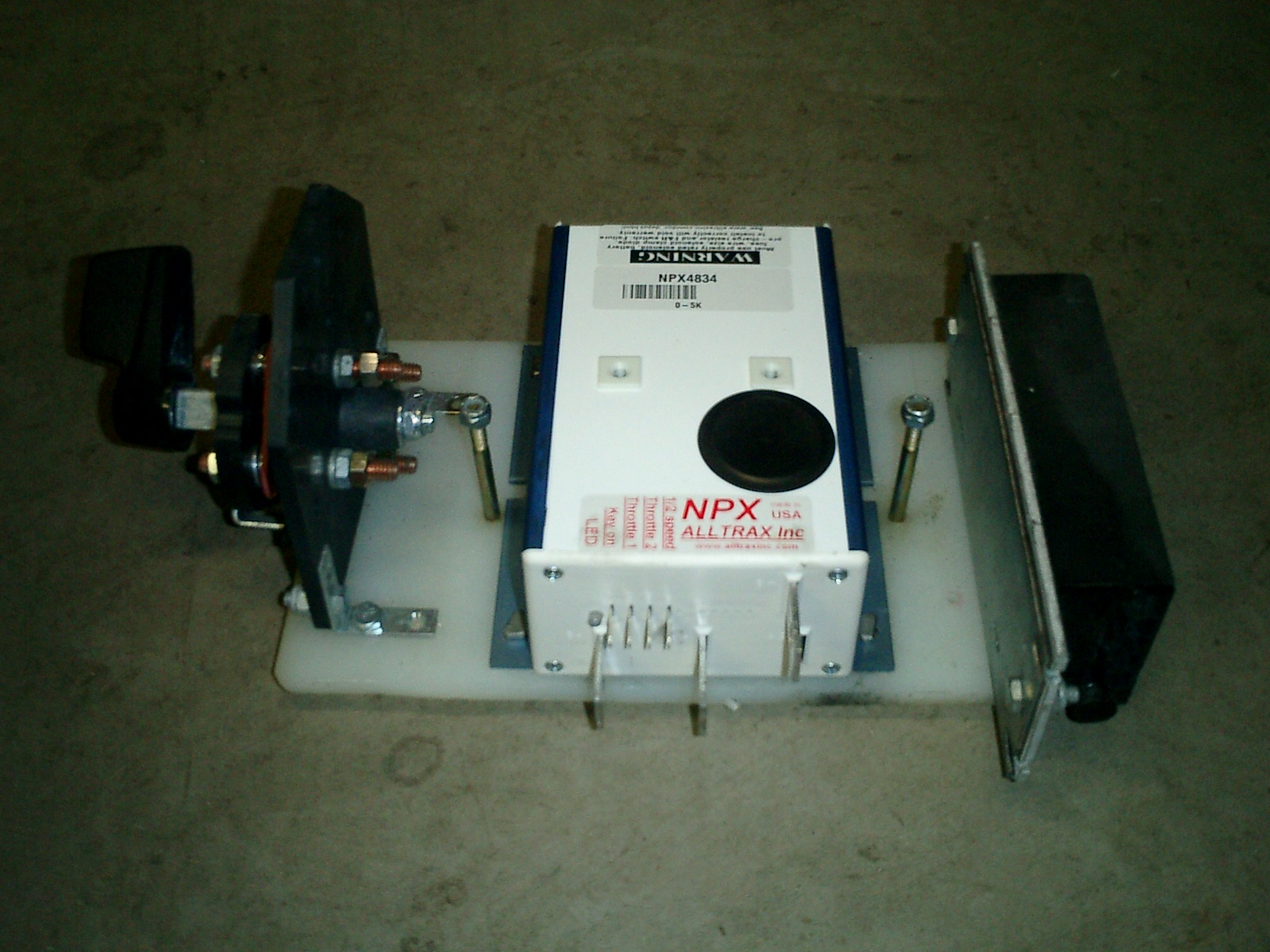
The reversing handle, speed controller and DC-DC converter are shown mounted to a cutting board using "L" brackets, ready to mount to the frame with the two bolts on either side of the speed controller. Using a cutting board not only saves time painting but it's corrosion proof too! You will notice that this DC-DC controller is an upgrade from the recommended one. This converter has a higher capacity than the basic one and is also isolated. This means it will be no problem to install a radio or some other high-power 12V accessory. Being isolated, it's much less likely to send a 48V surge through the 12V system should it fail.

Here is an image of the 48V wiring so far with the speed controller assembly lifted into place. Due to tight space, I found the lugs from the speed controller should be attached at right angles, then run under the reversing switch to come up where the battery tray is. To do this required using a Dremil tool to cut out a bit of battery tray although I also could have done so from the switch support instead. (see small square cut out on battery tray - to the left of the switch). To attach the lugs to the copper terminals on the controller and contactor, I use stainless steel nuts which I hope will resist corrosion better than the typical nut.

The wiring is also modified slightly from the plans. Two 48V wires needed to meet at a terminal in the contactor hump. However space was very tight there. So I moved the connection point for the two wires from the contactor lug bolt up the wire to the switch lug bolt. Electrically, nothing significant has changed. However, it's much easier to wire! Clicking on the image will show a larger version of the wiring diagram to show where I modified the wiring.

According to plans, the only thing holding on the motor cover is a strip of Velcro running down the trailing arm. I have found that's not sufficient since it's possible to go over a bump and lose the motor cover. So, I would recommend supplementing the velcro with a bolt as well. Just be VERY careful when drilling bolt holes for the cover. The motor has magnets in it so it's possible metal filings could be attracted to the inside of the motor causing BIG problems.
So, if the motor is already installed, before drilling, wrap the motor in plastic to prevent any metal drill filings from being drawn into the motor vents!

Tools used:
Razor knife
Dremil with cutting wheel
Adjustable wrench(s)
vice/hammer for making bolts
Bolt cutter
crimp tool
axe or large hammer (for crimp tool)

Parts used:
Wire Lugs 3/8 and 5/16 size for #4 wire $50 + shipping - ebay.
Electrical tape (3M brand)
Several lengths of #4 wire from wire spool (spool was $89+shipping)
(12) 5/16-18 Stainless steel nuts for contactor, reverse switch & custom controller bolts.
Around 6 inches of brass all thread to make bolts (since I forgot to pick up some at the hardware store)
Labor:
Around 3 hours.

Monday, September 29, 2008

Installing an inexpensive seat slider.


Since I've never driven a BugE, I don't really know what seat position would be the best. So, I decided to put in some inexpensive seat sliders in case my guess was off a few inches. By doing so, I also have made the BugE easier to service since the seat can be completely removed from the sliders. The locking sliders I used were from Northern Tool for a bargain price of $14 plus $8 in shipping. The seat sliders do not come with hardware. However, I found it was easy to create the hardware. If the sliders are mounted directly to the fender, there are some barriers to seat sliding happiness. In the rear, the knob that secures the fender to the fender hump prevents the seat from going back very far. In the front, there is a "glove box" hump that prevents the seat from sliding forward for taking the seat off during maintenance. So, the sliders and seat are raised slightly to clear these barriers.


Main part used:
Northern Tool seat sliders, A & I Slide Track for Model# ST100 - part# 11995
Note: Although these instructions are rather detailed, you may want to use another model of seat slider. I've noticed that Northern Tool has stopped offering the seats these sliders attached to. So these sliders may not be available for too much longer.

Pieces needed for mounting bottom rails to fender.
4- 1/4-20 x 1" hex bolts
4- flat head caps (included in kit) that were on the bolts which now hold the battery tray on.
4- 1/4-20 nylock nuts
8-aluminum washers 1/4"i.d. , 1"o.d. (o.d. can be more - aluminum is used since it doesn't rust)
a short length of aluminum pipe, at least 6" long with a diameter of 1/2" and a wall thickness of 1/16.

Pieces needed for mounting upper rails to seat.
4- 1/4-20 x 3/4" hex bolts
8-32 screw, nut & washer (if not included on handle in rail kit)
4- 1/4-20 nylock nuts
8- 5/16" washers (used for spacers between rail and seat)

Tools needed.
Socket or adjustable wrench (for driving hex bolts)
Flat head screw driver, medium size
Drill with 1/4" bit
pipe cutter for copper pipe
Vise
Reaming tool (or rat tail file & pliers)
Hex key (for flat head caps)

First, put sliders on the BugE fender & drill 1/4" mounting holes as if you were to mount them directly to the fiberglass. I put the rear holes lined up with the rear knob and front holes 9" further front. This was my best guess to where my seat would normally be. Of course, where you decide to drill holes is up to you. Just make sure rails remain parallel with each other.

To make the mounting hardware, I recycled some unused parts that were included in the kit. The black hex cap in the middle should look familiar. It's one of the four flat-head caps left over when the battery tray was installed. So these flat caps have found a new use. These caps can accept a 1/4-20 thread. Each of the 4 mounts consists of a flat cap, a (1/4-20) 1" hex bolt, two washers and some aluminum spacers that are cut from some stock aluminum. This arrangement will lift the sliders up and also give the clearance needed for the sliders to move properly by each other (inside the sliders, the tolerances are really tight). In the lower right yellow box, the new mount is shown assembled. The key to the slider mount idea is using an aluminum pipe to construct spacer parts. Aluminum needs to be used since the metal needs to be soft enough to cut yet strong enough to support the sliders & chair. On the upper right of the photo, one of these is shown installed on the rail.

To construct the aluminum spacers, use a pipe cutter for copper pipe. Cut from the pipe, 4 spacers 5/8" long and 4 spacer rings 3/16" long. Since the pipe may decrease slightly in size, the larger spacers may need to be reamed or filed so the flat head caps can slide through (see photo on right). The smaller spacers can be made by putting a flathead cap in the pipe as the ring is cut so the rings don't collapse. This saves a step since there is no need to file the rings to fit!

After the spacers are made, for each hole, take the bolt, put a washer or two on it to take up some length, then push bolt up through the hole. Then put on another washer, then put the large aluminum spacer on, put the rail on spacer, then cap off with the flathead nut (with smaller ring installed on it). Then tighten with an Allen wrench. You now should have some pretty nice looking lower sliders!

Then, mount the upper sliders to the seat based on measurements from the installed lower sliders. Careful not to get the sliders backwards! Note the position of the teeth in the lower sliders and handle on the upper ones. Loosely install the top rails to the seat with bolts, washers & nylock nuts. Then wiggle on seat to the mounted rails. If movement is stickey, add a small amount of oil. Once everything fits, jam each nylock nut with a screwdriver & tighten each bolt from the top of the seat. Then install supplemental padding in the seat if you want some & put on the seat cover which is included in the kit. The seat should now freely move back and forth & can be easily removed when servicing is needed.

Done!

Tuesday, September 2, 2008

The rear fender and battery pan

Here, the BugE frame sits right side up on saw horses. The BugE was shipped with some cushion material that was just right for stapling to the wooden sawhorses so the paint doesn't get ruined when the BugE is on them. Here, you see the grey material stapled to the sawhorses. The BugE has the rear sawhorse supporting the back and the front saw horse supporting the front. Moving the front sawhorse to this angle allows clearance so the battery tray can be dropped in to have a fender pan fitted to it. The rear wheel has been installed and the chain fitted to the motor. The car is getting a bit heavy but I can still lift he frame onto the sawhorses one side at a time. It will soon be time to move the BugE to lower jack stands to work on it further. For now, it's nice and high so it can be easily worked on.

Here are some images that show how the battery tray and rear fender were attached to each other.

First, some aluminum piano hinge was fitted to the front of the fender of the BugE using 8-32 screws. I decided to use those screws rather than rivets in case the top needs to be removed at a future time. The holes were drilled, then screws & nuts installed to make sure the hinge fit well & was centered. Then the orientation of the hinge was marked with a magic marker & taken off. Then, the other side of the hinge was mounted to the battery tray, centered, then screws were installed.

Then, an assistant held up the rear of the fender so the hinge could be re-attached to the rear fender using the screws and nuts that were fitted earlier. To the right, the image shows the attached rear fender held up by a garage rafter as it's being worked on. Next to the rear bumper-shock hump, a single 48V charger has been mounted with zip ties. However, this charger may move to the front with another parallel 48V unit if charging time is found to be too long.

Back to the rear bumper-shock hump. A reversing switch has been placed on the left. To get the switch to stand on it's side, some inexpensive "L" brackets were added. The brackets will eventually attach to the white support board using 4 - (1/4-20) - 3/4" bolts. The rectangular metal shaft on the left is for the reversing knob that will stick through a side hole in the fender. Since we now have a fender attached via hinge, we can lower it to take some measurements, then drill the hole.


There are several ways to measure where the hole for the switch control should pass through. At this point, the switch is not attached to the board. That way, if the horizontal measurement is slightly off, I can move the switch to meet it. However, the vertical measurement is critical. It was found by measuring the distance from the shaft to the bottom of the board plus the distance from the bottom of the board to the lip of the fender when it's lowered. The side hole can then be marked, then drilled using a hole saw. The photo on the right shows that the the fender was still rather close to the motor cover when it was put down so additional body material was removed using the Dremel. Note, you may want to secure the battery tray first and fit the rear fender knob to the rear shock hump BEFORE drilling this hole for the reversing switch.

In the image to the left, the fender is lifted off of the battery tray so a small square can be cut out where the emergency brake assembly can be attached. The large white thing is the fender in the UP position. On the right is a closeup of the cut out area which shows where the emergency brake will attach to the side of the car's frame. Here, we see the fender lowered over the battery tray. The parts all fit together nicely so the battery tray can now be attached to the frame using the flathead bolts provided in the kit.

The rear fender is off in this photo and the battery tray is clamped down to the frame. Drill material was left in the photo so the flat head bolt locations can be seen more clearly. Holes have been drilled down from the top of the tray to the frame. Then the exit holes were marked, then drilled up from the bottom. The flathead bolts go through the frame and are secured on the other side with 1/4-20 nylock nuts.

The front of the fender is normally secured by the hinge. The rear of the fender will be secured by a knob in the rear that screws into the threaded hole in the shock-hump. Then, some neoprene (provided with the kit) will be placed onto the shock hump so the fender can rest on it. The neoprene is attached with hot glue.

Pieces needed for fender knob.
1-Ace Lawn mower replacement knob
1- 1/4-20 x 1 1/2" hex bolt
1- 1/4-20 nylock nut

If you can find a low profile knob with a 1/4-20 thread, you can avoid this last step. Otherwise, here's how you can make a knob. The ACE lawnmower knob is female. We're going to make it male. Use a Dremil or hacksaw to to cut the nut that came with the knob out from bottom. Doing this should make a 3/8" nut fall out. Then, install a (1/4-20) 1 1/2" hex bolt and tighten to knob with a nylock nut.

Time used
Attach and install the battery tray & fender- 1 hour.
Add brackets to rear switch, then fit switch to fender - 1 hour.
Cut out fiberglass to allow for battery mount points - 1/2 hour.
Blogging about it 4 hours.

Parts substituted.
8-32 screws, nuts & lock washers instead of rivets.

Sunday, August 17, 2008

Mounting the electronics & rear wheel

Each kit is a bit different so expect some cutting and fitting. Also, I found that the order of assembly for my kit was somewhat different than what was specified in the kit. So I've found that it's wise to always be able to undo what has been done in case it needs to be taken apart again. Such was the case with installing some of the electronics. What I've written down so far is the way I would have put the kit together had I known then what I know now!

But first, it's time for more painting. I've taped newspapers all over the BugE so I can now paint the inside of the upper body (don't forget to block the fan so paint doesn't spray up) I'm painting the inside of the cargo area white (so my future cargo is easier to see) and a neutral gray for the rest of the inside. In the photo, it's about half way primed. Originally, I was going to paint the inside with stone paint I had left from another project. However, the paint didn't look too good on a test piece of plastic and I also noticed that it was not good for outside use anyway. So I decided to just stay with the gray. I figure if I don't like it later, I can always go the spray-glue & fabric route. I used spray paint for this step but I would not recommend it. It's very messy, expensive (especially since I went through an expensive disposable respirator) and somewhat dangerous since I was painting in the confined area in front. If I was to do it again, I would just use paint from a can and dab it on with a sponge brush. I decided to leave the front door on since I think the white paint in the middle, leaving red fiberglass trim on the outside may look nice for the inside of the door.

I also painted the bottom of the battery tray black. It's quick and boring so it didn't rate a photo.

Enough painting! Now go back to the frame on the sawhorses and turn it over so it's right side up. The tail for the rear wheel now droops down and the front tires are still off the ground. I recommend mounting the electronics first, then installing the motor and rear wheel after that is done. As you see by this photo, the contactor mounted under the rear bumper-shock hump is a really tight fit. If the motor and tire were installed, I could not even position my arm there or drill the mounting holes! Also, once the contactor is installed, it is very hard to tighten the nuts on top to secure the smaller wires because of the confining space.

So, it's much easier to pre-wire the contactor, put ends on them, then label the wires to show where they will eventually be connected. For reliability, all wire connectors have been soldered rather than crimped on. I don't want to take all this apart again due to a lose connection! Also, in the center, is a diode which has been wrapped in electric tape so it doesn't short against anything else. The lengths of wire are specified in the instruction manual and the circuit diagrams are excellent! Note, the big rectangular brown thing is a resister. I used one which has the same resistance but has a larger power capacity since that was what was available from my supplier. On the lower right of the left photo is the battery cut off switch with a removable red handle that serves as a primitive "key" for the BugE. On the right photo is the contactor once it has been installed, ready to accept two thick cables on the two large terminals.

Seen in the front of the right photo are the two bolts that would have been impossible to drill had a tire been installed. Also, if the motor was installed, it would have been impossible to wedge the contactor into it's mounting space. The contactor was mounted using 2 - 1/4-20 x 1 1/2" bolts & nylock nuts and the left mounting hole was drilled using an angle drill adapter (since the drill I had was too fat). If you're wondering about the Velcro, that's for the motor cover and mud flap (other parts I would install later since they need to be taken off to do these next steps)

Here, you can see the speed controller which is mounted to a piece of white plastic under the front hump of the bumper-shock assembly. Use a jig saw or table saw to cut a board 7"x12" piece of 1/4" plastic or finished plywood. (I used an old plastic cutting board cut to size so I wouldn't need to paint it). Mount the controller to the board using 4 - 1/4-20 x 3/4" bolts with the controller's row of spade connectors facing the rear of the vehicle. On my kit, the space was really tight for the controller so I used a grinder to grind off one side of the hex head bolts so the whole unit would fit inside the frame area.

The board forms two shelves. On the BugE models with the reversing motor, the near side would hold the reversing switch and the far side was supposed to hold two 48V chargers (more on this below). The frame is resting on some seats of some old chair cushions. I used these since I noticed using saw horses with no cushioning was destroying the paint every time the frame was set down on them.

There is another issue that I think is specific only to my kit. I had no tab for attaching the hose clamp for a rear motor mount. I expect this was due to the welder forgetting to weld on the tab. I wasn't sure how critical this was to the design so I decided to construct a bracket and hose clamp arrangement to mimic the function of the missing tab. The hose clamp I used is a 5" to 6 1/2" size attached to a bracket of scrap metal and two bolts. A consequence of this is that the motor cover will now need to pass a bolt (probably using a hole and rubber grommet). However, there is a good side to this. The motor cover, secured in this way, is much less likely to fall off!

Now, it's time to put on the wheel, motor and rear mud flap. The manual covers this rather well so I won't bore you with the details. However, I did take this pretty picture of some parts. The MT-2109 motor from EV parts includes the sprocket, key & motor mount bolts. It fit the motor mount perfectly. The motor isn't too heavy but watch your back anyway. The red box is the drive chain that is included in the Bluesky light & control kit. The other flat bolts were also from the main kit and will be used to securely mount the battery tray to the frame.

POST CONSTRUCTION NOTE:
In the instructions, the motor cover is supposed to be held on to the swing-arm only by Velcro strips. While Velcro alone may work for a few weeks, eventually, the motor cover will vibrate off. In my case, when I hit a pothole. So, my motor cover now has an additional bolt & nylock nut that passes through the top of the motor cover and the rear wheel swing-arm. Since doing this modification, I've had no problems with the motor cover being lost.


My kit came with the large gear already on the rear wheel. Pictured is the rear wheel assembly. Just like the front wheels, the rear wheels have drum brakes too. The axle is also included. When putting on the wheel, just be careful that the brake slot fits with the tab on the frame. When putting on the wheel, it sometimes wants to slip out until the bolts are tightened down.

Now that the rear wheel is on, you need to connect it to the motor gear. To make the chain the proper size for doing this, it's just like how you would do it on a bicycle. Just use a block of wood and a hammer to force the rear wheel in on the frame. Then put on the chain & mark the link which would give the desired loop length. Grind off one side of that link so the chain is shorter. Then put in the provided master link so you have a loop. Then, use a block of wood and a hammer to force the rear tire out so the chain has some tension on it. I'm not sure how much chain tension is good nor the torque values on any bolts so I've been going on "feel". Providing torque values on critical parts such as the rear bolt would be a nice addition to the kit instructions.

The motor cover and mud flap should be mounted last since they need to be removed to provide access to other parts if mounted earlier. When installing the mud flap and motor cover, I found I had to trim both to fit properly. However, they were both very easy to modify using a Dremil cutting wheel. Then I put on Self adhesive Velcro in various spots to hold these parts to the frame. Later, I resorted to an 8-32 bolt and a bent coat-hanger to hold the plastic piece against the motor wall. This solution is not too elegant, but it is effective.

Since I'm doing the reversing motor option, the supplemental instructions show an image of two chargers stacked on top of each other instead of on either side as would be the case for the forward only motor plan. However, there is a problem with the instructions. I found the units included in the deluxe EVparts BugE kit were much larger than the ones pictured in the manual! So, I'm resorting to using a 48V external charging port instead and the shelf will now be used for mounting a DC-DC converter.

That's all for now.

Wednesday, August 13, 2008

Frame, suspension and steering.

While the cowl paint is drying, other things can be done.

First, the shock is installed on the frame. The default shock strength is set to a reasonable setting straight out of the box. No need to buy the bolts and nuts as they are included. The bolt holes were just a pinch too small so I had to use a rat-tail file to make the holes just a bit bigger. Note, the photo was taken with the old paint job. It was at this stage when I found the first hint that the old paint job might need to be stripped off. When I started adding on other parts, the paint started chipping and it was clear I had to redo the paint job. However, when the new paint was applied, the parts went on the same way.

The rear swing arm assembly was reassembled as it was when it was shipped. Since some bolt threads were slightly damaged when I pounded it out for painting, I had to repair it. A jewelers file was good for doing this. Otherwise, the swing arm assembly went together just as it came apart. I added a pair of 12mm washers to the outside swing arm bolt assembly so the paint job is protected a bit more than it is in this photo. The swing arm and bumper bolts stick out but are harmless to leave in that state.

The frame was then turned upside down. The brass bushings for the steering spindle were gently tapped in with a hammer and then attached to the front of the frame. The tie rods and the stabilizer rod (below the tie rod) were then installed. On steering arm, some 5/16 washers were added as spacers to allow free movement of the tie rods.

Post construction note: I originally had a stabilizer bar. However, the shock mount needed additional clearance. So, I could no longer use the rod. Instead, I created a retrofit that uses sliders instead. To date, this design change has worked well. The refit can either be installed at this time or at a later time in the assembly process. The upgrade can be seen HERE.


Put the front wheels on the steering spindles
The kit wheels and brakes parts are made by Tomas, one of the largest moped manufacturers in the world. The wheels come as a unit which includes a drum brake setup for each wheel and an integrated wheel bearing. The rear wheel also has a custom sprocket attached for the chain drive. Replacement wheels used to be available at http://www.tomasusa.com/. However, TOMAS A35 5-spoke mag wheels are still available HERE (both front, back and used ones). Replacement brake pads take an EBC-525 shoe. Another part number that would work would be a H302 which fits a Honda sports bike. The tires are moped tires that measure 2.50" - 16". The first measurement is the height off the rim. The second measurement is the rim diameter. Another acceptable tire is NR21 300-16 UNIV REAR STD from http://motorcycleproshop.com/ .

When putting on the front wheels, a tire adjustment will be needed. This is because a three wheeled car, using two wheeler parts, will have one wheel tread “backward”. (the “arrow” on the side of the tire will be going the wrong way & tread will be backwards). Although it is possible for a person to change this with hand tools, having it done at a motorcycle shop is much easier since they have a special machine made just for that. However it is done, the tread needs to be reversed, then the tire re-inflated to 35 PSI.

Another issue is that the wheels are secured to a bare axle with a castle nut (and cotter pin). I noticed that the hole for the cotter pin on my kit was rather far down the bolt on the steering spindle. So, the eventual solution is to drill another hole closer for a cotter pin. However, the spacer method using washers is used for now so a wider wheel can be easily tried later. The last photo shows this temporary modification of the wheel hub using washers as spacers. As for play, the tightness of the bolt is 1/6 rotation less than snug. (so wheels freely rotate w/o much wobble)


Once the tires are in place, it's time to adjust the tie rods. The recommendation is to have toe-in of about 1/2" so the tie rods don't bend. (that is, the front of the tires are 1/2" closer than the rear of the tires. After this is done, it will be time to mount the rear wheel and motor.

If you are wondering how long this is all taking, I've itemized it below. However, time estimates for this project will vary dramatically from one individual to another. Three things extend time more for me. First, I'm blogging as I go so everything takes longer since I'm deciding on photos & verbage. Second, I'm keeping track of every part purchased and used plus adding notes as I go. So journaling all that takes time. Third, there are some pauses for decisions. For example, do I install a fan, two fans, 5 fans? How many coats of paint should I use for the frame? What shock mount position should I use? Should I drill out another cotter pin hole (and cut off the excess bolt) or do I use spacers? Do I use the DC-DC converter or an extra 12V battery or both? (and if I use an extra battery, what kind do I use and how do I mount it? All these little decisions and debates take time. If I was to do this again, I'm sure this vehicle would take much less time to assemble.

Time used
Re-assemble frame - 2 hours to assemble and cut off any excess bolt lengths & fix threads.
Installing steering spindles, tie rods & stablizer arm. Then align. - 2 hours.
Taking wheel to motorcycle dealer for retread, research & order extra brake parts - 2 hours
Keeping track of parts & ordering additional items needed later - 1 hour.
Installing fan & painting (previous posting) - 1 1/2 hour
Blogging - 4 hours.


Additional materials not specified in the kit
(8) washers of 1/2" ID for wheel mount modification
(2) 12MM washers for rear swingarm
(1) pair of EBC-525 pads for front wheels for spares - $14.95/pair


More painting & installing a vent fan.

In the plans, there is a step that mounts one or more fans in the cowl. The default placement is a single fan placed in the middle of the cowl. On hot days, the fan might be able to provide some small relief from heat in traffic. On cooler days, this fan, combined with anti-fog and RainX should keep the winshield clear.

To install, note the arrow on the fan that shows direction of air flow. Then, take off the exhaust grate. Then, use the metal grate as a template to mark out holes in the cowl. Use a PENCIL, flexible measuring tape and some geometry to get it 12” from the front & placed in the middle. Then paint the grate black so it doesn't reflect in the winshield and while it's drying, do the other steps below.

Use a DREMEL tool Drill BIT on HIGH to carve out the basic shape & drill holes for the screws. Since this is one of those one-shot moments, go slow. Just follow your pencil marks from the previous step. Try the tool in the middle first to see how the tool works. Then, work your way out. I found the drill bit was good for rough cutting in addition to drilling the fan mounting holes. The DREMEL drum sander worked well to smooth the edges.

Mask with tape and newspapers. Then gently sand, then paint. In addition to the cowling, the area that could be an instrument console has been painted too. Initially, surface mounted insturments will be used. This will allow for easy adjustment as various ergonomic placements are tried.

Since the fan is on the bottom of a curved surface, ¾” long, 9/64 diam. screws (and nuts) are used to secure the fan instead of the recommended sheet metal screws. Pictured here, the image shows the longer screws & nuts on the left that were added so the fan could be installed easier.


Next, the outside of the battery box was painted gloss black. Since it's not very visible, gloss or matte black can be used. As for more finishing, the inside of the body needs to have a finish rather than just the reddish fiberglass color. The finish should look nice, be water resistant and not be too expensive. I'm thinking stone although rubber undercoat has been suggested as well.

Friday, August 1, 2008

Enough hype - how much money would I save?

There has been a lot of hype when it comes to how much an electric vehicle costs. Such false claims make it so people have much higher expectations of an EV than they should. Some cite figures as low as a penny a mile, which may be true if just counting JUST the electricity but that does not cover all the costs.

So, here are the true costs I anticipate having for my EV

ENERGY COSTS
The cost of electricity is really quite inexpensive. The often cited figures of $0.01 a mile that electric car owners often cite are probably not that far off. For a full charge, the BugE is rated for around 1.5KWH. My electric cost is around $0.08/KWH, so that's $0.12. To put things into layman's terms, to charge the BugE, the charging unit takes around the same energy it takes to leave a porch light on at night.

OPERATING COSTS
What some people forget when citing EV operationg costs is that lead acid batteries are "used up" with every discharge cycle.For example, for the BugE, a full set of Optima D34M-950 batteries should be around $760. They are rated for 300 full cycles (or more partial cycles if I don't discharge them as much). I'm expecting a full discharge could give as much as 20 miles at 30mph under ideal conditions. If I go half the distance before charging, I may not do as much damage, so I may be able to go more miles. If I go faster, wind resistance becomes significant so I can't go as far. So, analysis is rather difficult unless some standard of performance is assumed. So, let's assume a full cycle, 20mi at 30PH. So, assuming 300 cycles, that would be 6000 miles before I would replace my battery pack. If we assume a new battery pack (with shipping and/or taxes) costs $800 and divide that by 300 trips, we get$2.66 per trip. Adding in the cost of electricity for the trip, we get $2.78. So, it would be like I had a car that got 20mpg paying at least $2.78 for petrol. I qualify that figure since hills and irregular speeds would decrease the range per charge by quite a bit.

What this shows is that a BugE might save money if gasoline starts going above $3/gal but it's hardly a revolution in doing so. Plus, I'm giving up quite a bit of performance to get the cost savings. However, if I did a full size conversion, I get more performance but per-mile costs go up too since I'm hauling around more vehicle as I go each mile. So, if I was to do a full size ev-conversion using 4x the batteries, that would mean roughly 4x the cost to go the same number of miles. No wonder we don't see many EV's on the road!

Of course, different packs have different costs. Lithium is more expensive but also has a longer service life with better performance. My personal favorite is the Edison nickle-iron design. Those cells are pricey but they have better performance per lb than lead and boy are they are tough! Some nickle iron batteries used in the railroad industry have been in service for over 30 years! Using those batteries would make the BugE significantly more favorable as a transportation solution. Unfortunately, I am aware of no nickle-iron pack in a size suitable for the BugE.

REPAIR COSTS
So, if I'm not saving money by using lead acid batteries, why bother? The repair costs are where I anticipate big cost savings will be. This is because several systems such as exhaust, cooling, climate control, transmission, ignition, airbags and other expensive accessories do not exist (if they don't exist, they are totally reliable). I'm accepting that more little tune ups for the BugE may be needed, especially in the first few weeks of operation. However, the fixes will be rather simple and inexpensive compared to maintaining a petrol car. I am also expecting that the maintenance cycle will be different than on a regular car. For example, I would expect tire lifetime to be similar to motorcycle tires which tend to be replaced every season. Since the BugE extends the season, the tires may need to be replaced twice a year. Although this is more often than automotive tires, the BugE tires are only $20/ea. and of course, I only have three of them. I may also have more wear on the rear tire since that is what propels the vehicle. I'm assuming the wear on the brake pads would be similar to a motorbike, which should probably last around 10,000 miles.

INITIAL COST
I have been tracking my expenditures rather closely. So far, I've spend $8100 in materials and anticipate spending close to $9500 when I'm done. This includes all materials, batteries, & additional tools I had to purchase for the project (such as the tool chest). I am also including materials that I lost to mistakes (such as the expensive galvanizing paint, stripping & repaint materials). As for trips to the stores, I'm satisfied claiming $5/retail trip. So with 20 trips, that comes to $100. If an online purchase was done, the shipping cost was included. If purchased via retail, sales tax is included. I am NOT counting tools I already had such as screw drivers, pliers, socket set, a 4" grinder & small Dremel set. (I think all tools I've used so far would be safely less than $300 - especially if shopping at places such as Harbor Freight.) If building more than one BugE, I'm sure there are significant savings that could be had by buying materials in bulk and splitting the cost across many units.

LIFE EXPECTENCY
There are lots of unknowns in this area. Hopefully, the BugE will be driven in the rain more than a regular motorbike. It also can be driven in the winter on days where there may be no snow, but where salt may be on the roads. So this may lead to more corrosion problems than I would see with a regular motorcycle. The canopy, could become scratched over time with multiple applications of RainX. The controller electronics, although simple, will be in a cold moist environment so they may not hold up too well. The motor in theory should last a long time.

Thursday, July 24, 2008

Seemed like a good idea at the time....it's not.

George Washington said, "Experience enables you to have good judgment. Experience comes from making bad judgment." Such is the case with my paint job. Lots of effort and expense, only to strip it off. I started noticing a problem when I mounted the shock. By the time I got to the steering, it was really getting bad. It turns out that the base coat of galvanizing compound is very weak. Little specs are flaking off, taking the top coat with it. So, I have the opinion that it was better to deal with it when I can get to the entire frame rather than taking it apart later.

So I made another trip to the hardware store to say goodbye to around $100. This is for two cans of stripper compound, scraper, metal brushes (large and small) and disposable respirator. In addition, I bought more primer and paint for a second try. All this, with drying time, took two days to strip and another two days for drying time (although paining itself only took 15min per coat).

Hopefully, you won't need to take paint off metal. However, if you do, using paint stripper gives good results. Paint stripping compound is amazing stuff - but very dangerous! Within a few minutes of spraying it on, I found the paint and undercoat turned into a goo that could be scraped off after a few passes. Just don't scrimp on the safety gear! Wear safety glasses, mask and spend a few bucks to get the special stripping gloves (rubber dish washing gloves are NOT good enough). I would also recommend wearing nitrol gloves underneath these too. Why? Just one tiny splash of that stuff burns! I found when I splashed just a tiny particle of the stuff on my arm, I had to wash it off quickly due to the pain. Fortunately, I had a working garden hose handy to flush off the occasional drop that would land on me - and I used it several times!

So far, doing the paint job again has cost around $100 in chemicals and disposable tools plus
1 hour shopping
3 hours stripping rear assembly. 7 hours stripping main frame. Prime and paint take 15 minutes per coat - but drying time is over 6 hours. So, that's a minimum of two evenings and mornings.
After repainting the bug, I found that the paint looks about the same but it's much more durable. I do wonder if undercoat material would do even better. Ah well, perfection is the enemy of progress.

Monday, July 21, 2008

Time out for better inventory control.

I know I'm obsessing about parts, but I want to track them better. So, I now I am using parts drawers and a labeler to go along with the database. Now every time I check a small part, it goes into it's own clear plastic drawer with a label. Large parts still go in the big toolbox. I've found that checking in parts slows things down, especially since I need to make the database agree with the receipt from the store (which isn't always clear) and finally the label on the drawer. However, it hopefully will save quite a bit of time later when I can just grab a part rather than make a special trip to the store just for being one part short.

This system also provides a method of keeping track of substitutions where used and difficulties getting parts (eg, Perhaps a store carries it, but they are out of stock and a substitute may be available from an alternate supplier). Many of the substitutions are for more robust versions of a part (eg using #12 instead of #16 wire). Others may have bigger consequences (eg. The somewhat experimental galvanizing treatment I'm using). For each part, the database notes where it was used, how many ordered, unit cost, unit packaging (eg. 6pack, box of 20), sales tax, shipping paid, steps the material or tool is used in and if it's a substitute from the original specification. Later, I'll be editing the database as I find a trade off between the expense of collecting info for each field and the cost or time saved by having it.

Entering the remaining small parts plus labeling took about 16 hours (over two full days) to represent them correctly in the database as well as being categorized so I can pull them quickly. Blogging took about 2 hours. Naturally, when I get faster at knowing what parts look like, this time will go down. I'm sure at the end of the project, I'll find some efficiencies. Time will tell if these efficiencies are worth the effort to get them. (it may not be - in the case of small nuts, it's less expensive to just buy a quantity that is known to be more than enough) I might be short a bolt or two but it looks like most pieces and tools except for the Optima Blue Top batteries are now on site!

Further parts should come to about $500. I think a blanket $500 statement should be more than enough to account for materials I may have forgotten and parts I may already have in my shop - which I'm also tracking.

Tuesday, July 15, 2008

Tracking resources used.

One of the most important items in my shop is a new roll away tool chest that acts as a mini office. It is used to store all the parts, paperwork and revised instructions having to do with the bug. Every screw, nut, material and accessory is checked in as if it was being stored in the cart. Should I decide to build another BugE after this one, the second one assembled would go quite a bit quicker since I'll have records to allow me to easily combine orders and compare supplier pricing!

I'm also revising the manual to be more complete and that takes quite a bit of time and effort to do right.

If you are going for a tool chest, don't bother with the cheap ones at Lowes. Get at least a Craftsman tool chest. If you get one, spend a bit more for ball bearing or "quiet glide" drawers. The price may be only be slightly more if you catch a sale (and there's always some sort of sale at Sears). In my opinion, not hearing the cheap drawer slider noise and the convenience of the rear lock bar is worth the extra bucks. Plus, they seem to be made better and have large casters that can go over most anything.

Currently, my system is to take a guess on the materials needed for each step. (parts are listed, but there is always SOMETHING missing, even if it's something like a paintbrush). Then, I keep all receipts and using a custom MS-Access database, I check items into the figurative tool box. Then, when I have enough materials for a step, I'll try to do it. Any additional items I put in, I record and check in just as if I bought the items beforehand.

At this point, entry is not too efficient since I'm not sure what's important to track and what's not. I'm recording everything I can, even alternate suppliers and possible substitutions if I see the item available elsewhere. The database is relational so it's very easy to add/drop features to it. I'll have more news on that later.

Establishing the database was made easier by modifying a template from MS-Access. Time to modify the database, I would estimate would be about 8 hours to get it right for my use. Fortunately, I'm not in too much of a hurry so I don't mind spending some time thinking about my needs, then modifying a database to record them.

Saturday, July 5, 2008

Unpack and paint some parts

Finally! Time to start! The first task is to paint the chassis and rust proof it so the vehicle doesn't rust away during the winter time when salt is applied to the roads. Unfortunately, the garage flooding was rather hard on the EV to be. A mild coat of rust was forming outside (and probably inside too) so I felt that simply coating the frame with paint as per the assembly manual was not an option. Doing so would just seal the rust in. So, I decided that a zinc based compound should be applied in the hopes that the zinc would rust before the steel does. The compound of choice was a product made by LPS (1-800-241-8334). It's an aerosol can product called "cold galvanize corrosion inhibitor" that claims a zinc purity of 99%. Using this coating is an experiment. However, I'm willing to try most anything to prevent roadway salt from eating my bug!

So, to paint, the first step was to unpack the bug components. The upper supports on the shipping crate were quickly sawed off with a portable reciprocating saw and lifted off. Then, the fiberglass body was lifted off. The shell isn't too heavy but I feel it's beyond one person to lift it off safely. Fortunately, with two people, it's easy and only takes about 5 minutes. After that, the other parts were unpacked and rear fiberglass housing and battery tray were then taken off. The last component to be taken off the pallet was a two-piece steel frame which was attached to the pallet with two giant wood bolts. Once all the parts are separate, they can all be moved by one person.

The two piece steel frame was detached from the pallet, then taken apart. This was not easy. I found that the large bolt holding the two main frame pieces together needed to be hammered out with a railroad spike. Then, a 1/4" drill bit was used to drill holes in various places under each frame piece so zinc spray could be applied via a straw. To do so, the aerosol nozzle of the zinc compound was replaced with a different spray nozzle that can accept a small plastic straw. Note, a WD-40 nozzle spray top has the wrong spray can "gender". Fortunately, I had a key lock lubricant which had the correct gender and straw. Painting was done in a low cost kiddie pool to catch drips from the zinc compound. After the paint straw was removed, 1/4" rubber grommets were applied at each access hole. Hopefully, each access hole will allow water to drain so rust doesn't form as quickly from the inside as it would without treatment.

Since there is quite a bit of visible but mild rust on the outside of the frame, a chemical approach was used to remove it. The chemical of choice was naval jelly, available in most auto stores. It dissolves rust but not the rust-free steel. As the rust is dissolved, it can be scrubbed with a wire brush and then the compound is washed away with tap water leaving bare metal. The parts look great after doing this but they are very vulnerable to corrosion so they must be coated immediately after washing off. The parts also had oil left on them from drilling holes for anti-corrosion steps so the parts needed to be washed further. The parts were set in the kiddie pool located in the driveway and lacquer was applied by brush. Some internal galvanizing compound broke down when exposed to the lacquer so the parts didn't look too clean. However, the parts were clean enough to accept the galvanizing compound. Disposal of the lacquer was not a problem. It was a hot sunny day so the used lacquer just evaporated on it's own.

Next, I put the frame parts back on the pallet, put on the respirator and started spray painting. Since I ran out of galvanizing compound, I finished the job with Rustolium's corrosion inhibitor product. I found the Rustolium product didn't cover as well and tended to run more. Also, I've decided to use a different color primer rather than gray so I can tell I've entirely covered the gray anti-corrosion layer. I've also decided to go with a shiny finish on the frame instead of the matte black color since I suspect it will repel roadway grime better. The matte black spray paint I already bought will now be used for the console area instead.

For painting, I was originally going to use spray primer then coat with spray paint after. However, after reading the labels on the cans I had a problem with that approach. Turns out, many primers don't bind to galvanized metal! I didn't want to take the chance the galvanized paint would act like galvanized metal (in terms of paint retention) so I looked for other alternatives. Fortunately, Rustolium made a black enamel paint for appliances that didn't have the galvanized metal warning. As a bonus, it even recommended that the paint be applied direct with NO primer! The finish looks OK. Hope it is as durable as it seems!

There is something more I should mention about painting for any would be bugE builders. Since my neighborhood has a homeowner association, they have rules on keeping the neighborhood tidy. So, with the assistance of a home made dolly, I just wheel the whole pallet out of the garage to paint, then wheel it back in to dry!

Step Summary:
1) Take off cardboard. Check in parts against packing list. 1/2 hour
2) Detach bug parts from crate & set asside parts that don't need to be painted. Then take apart frame for painting. Document (or take photo of) tie rod ends & rear shock - 1 hour
3) Drill 1/4" holes, apply anti-rust compound squirting compound inside holes, swishing around compound inside frame, then apply grommets - 3 hours (and overnight to dry)
4)Apply naval jelly to remove rust from exterior. Then rinse to remove 1 hour.
5) reapply naval jelly again, grind & scrub if rust is severe 1 hour.
6) Set in kiddie pool and apply lacquer thinner to all exterior surfaces to prep metal for treatment 1 hour
7) Apply zinc corrosion inhibitor to top side 45 mins (then wait > 3 hours to flip)
8) Apply zinc corrosion inhibitor to bottom side 45 mins (then wait 8 hours)
9) Apply black enamel spray paint to exterior on top. 45 mins (then wait 8 hours to flip)
10) Apply black enamel spray paint to exterior on bottom. 45 mins (then 8 hours dry time)
13) Reassemble bug frame & parts according to images taken before disassembly & put on sawhorses. (haven't done yet)
14) Blog about it - Est. about 8 hours at various points during the week.

Tools used so far...
Reciprocating saw
Socket set (for detaching frame from pallet)
Screw gun (for detaching bug from pallet)
Drill (and 1/4" bit)
Respirator, safety glasses, earplugs
Screwdriver, hammer, railroad spike
sawhorses, kiddie pool
paint brush and a throwaway container for jelly and thinner, coat hangers & rags.
Shipping pallet & home made dolly

Purchases - HOME DEPOT - Tax not included:
1 - box Nitrinol Gloves 2.99
2- Rustolium 12oz primer spray paint 3.97 ea. - 7.94
2- Rustolium 12oz matte black spray paint 3.97ea - 7.94
1- pt. Lacquer thinner 6.69
2-sets respirator filters 15.49ea - 30.98

Purchase - Toys-R-Us - tax not included
1 - kiddie pool - 7.99

Purchase - Radio Shack - tax not included
2- Vinyl Grommt Kit assortment (Part 64-3025) - 1.99ea - 3.98

Purchase - Home Depot - tax not included
1 -Rustolium Corrosion inhibitor
3- Rustolium 12oz black gloss enamel spray paint 3.97 ea. - 11.91

ACE Hardware (Suburban Hardware) - tax not included
2-LPS galvanize spray 12.49ea - 24.98
1-Naval Jelly 3.99

AutoAnything.com (free shipping)
2- CIPA Lighted Euro Sport Side View Mirrors - 49.95

Friday, June 27, 2008

Scavenger hunt...

It rained last night. However, my secondary dike behind the garage door retained the water! Yay me! I really wish I had some "before" photos to show how much my work area has changed. At this point, I'm taking a look at the instructions and getting the most obvious hard-to-get items on their way to my house. For me, since I live in a sort of rural area, the cost of the item is mostly the transport. Basically, if I need to get something, even the smallest screw, I have a $10 premium of petrol and my time that I mentally add onto the cost. When taken in that context, shipping to my door doesn't seem that expensive given what gasoline prices are. Thank goodness for online ordering!

Here are today's items (including shipping):
JigSaw, Blades, 1/2" wire wrap, 1/4" wire wrap - from Harbor Freight - $44.16
Headlights (going with the standard choice) - NV-503W from TruckAndVans.com, $48.03
(Just one set for now, but I may eventually a second set for high beams)
Seat rails (optional, but I want to do it) - from NorthernTool.com, $22.98
Metra Tsunami Premier Gn604-75 Ground Cable #4 AWG, BeachAudio.com, $82.99
Power cable lugs (25) for #4 wire, 3/8 connector, Ebay, $14.50
Speedometer (illuminated/wheel pickup/odometer) Koso XR-SA from dynotunenitrous.com, $136.90
Items from Salina Electronics (a local retail electronics store)
1- 470Ohm 10Watt resister (10W_470Ohm 5% 10W147-nte) $1.19
1- Suppression Diode (1n4004-NTE) $0.05
1- 6 Amp Diode (R-100PRV_6A 5812-NTE) $1.84
1- 5 Amp Fuse (AGC-5A-BUS 3AG-5A 312005-LIT) $4.80 (5pack)
1- Inline fuse holder (150145-LIT - or whatever matches the 5A fuse) $2.95
3ft (or package) of Wire wrap 3/4" diameter $3.78
1 roll 3M electric tape $1.89
Shipping (car trip) about $3 in gasoline.

Whew! Other items such as the handlebar and mirrors I'll wait on for now. I'm still searching for a decent mirror and turn signal combo. However, with the exception of the batteries, I'm now down to items I can get from the hardware stores in my area. Although fasteners such as bolts and rivets tend to be inexpensive, the trip to the store isn't. So, I'm spending some extra time to come up with an accurate pick list so I can combine trips whenever I can.

Total time ordering (and blogging to tell about it - around 10 hours)

POST CONSTRUCTION NOTE:
This is not a recommended shopping list, just what I happened to buy. Some of these items such as mirrors and lights have since been upgraded to meet DMV requirements. Buying too much expensive #4 cable also drove the overall cost of the vehicle up since I bought a whole spool rather than the lengths needed. If anyone is building a BugE, let me know. I have enough cable and ends to make up several several cable sets for the standard BugE motor & controller with reversing option.