Monday, January 26, 2009

Installing the speedometer pickup

POST CONSTRUCTION NOTES
These notes only apply to pre-2009 BugE kits that have drum brakes. The new BugE kits now come with disk brakes.

The speedometer kit came with a speed sensor, mounting bracket and several magnets. The instructions covered programming the unit rather well, but it did not cover the more mundane task of mounting the sensor!

In the image to the right, the sensor is shown mounted in the bracket. A hex wrench is used to secure a set screw for the sensor. The kit also came with some tiny rare earth magnets (circled). To mount the sensor, I used a 1/4-20x3/4" hex bolt and two washers left over from a Radio Shack grommet kit (Part# 64-3025). Earlier in the BugE steps, I used the smaller grommets from the package to protect the holes when I was filling the frame with anti-corrosion paint. Since I did not use all the larger sizes, I had quite a few left over. Inside the yellow square, a 1/4-20-3/4" hex bolt is shown cut to 3/8" long plus a washer can be seen. The other nut/bolt is shown so the original bolt length can be seen.


The left most photo shows the speedometer arm balancing on the steering spindle pin. The bolt & nut are held in the mounting arm tight due to grommet#1 filling the space. The sides of the hex nut have been filed down slightly so it will fit tightly in the brake channel. Once the brake assembly is pushed back onto the steering spindle, all the parts are held together by pressure. Grommet #2 was added for a tighter fit. Once the bracket is in place, the sensor is mounted to the arm using a set screw.

The next step was a bit messy for me. There is no place for the magnets on the BugE tires. I didn't want to weaken the wheel by drilling little mounting holes so I figured that the little magnets should be glued on. The product I used was J-B Weld. There are three reasons for this. First, the mounting material should be strong. Second, it should be resistant to water. Third, and most important for me at the moment was that it was cheap. Fortunately, I had a box full of glues, epoxies and calk collected over the years. So, I punctured the tubes, mixed the product and it worked. I was impressed. I'm pretty sure the "new" pack I used was at least 10 years old!

Once the epoxy dries, I put the wheel back on. Then I used a Dremil tool to drill a square hole through the wall of the BugE large enough, and square enough for the sensor wire end to go through. Then, I took a small grommet & split using a razor blade so it can go around the cable. Then, I took a larger grommet & work it over the connector, then put the larger grommet over the smaller split grommet. Then, I stuffed both grommets into the square hole which will took up the space around the cable. Hopefully it will hold. I'll be watching that cord. If it wanders around too much in the wheel well, I may use some split tubing to force it to take the same path up as the brake cable.

At a later time, the speedometer needs to be calibrated. Since the instructions that came with it cover this step, I won't go into detail on how the unit is programmed. Just as well since instructions such as that usually differ from unit to unit.


Kit Materials used:
(From speedometer kit) mounting bracket, sensor, magnets, hex wrench

Additional materials
  • (1) 1/4-20 x 3/4" hex bolt & nut, cut to size
  • (2) grommets left over from the earlier anti-rust step for arm
  • (1) large grommet, (1) small split grommet for speedometer pass through.
  • (1) J-B Weld epoxy package
  • (1) set nitrol gloves (for the epoxy)
  • (1) stirring stick & disposable mixing container
  • zipties
Tools used:
  • 3/4" wrench to take off wheel nut
  • Hammer to hammer out cotter pin
  • needle nose pliers to convince pin to come out of the axle.
  • Vise to hold hex bolt for cutting & hex nut for filing down
  • Dremel tool (with cutting wheel) to cut down hex bolt to desired size
  • File to remove material from the sides of the hex nut so it will fit in the channel
  • ruler & pencil (to measure where magnets go so sensor can pick them up)
  • Drill & drillbit (for passing through sensor wire)
Time used:
  • Jacking up the wheel, taking off cotter pin, castle nut & wheel washers - 15 minutes.
  • Imagining a solution & test fitting parts together - 20minutes
  • Cutting down the bolt & grinding the nut to size - 15 minutes
  • Mouting arm to wheel - 15 minutes
  • Drilling hole through body for sensor cable - 15 minutes.
  • Securing wheel with castle nut & cotter pin, then removing from the jack stand - 15 minutes.

Sunday, January 25, 2009

BugE bumper probem - and solution

REDO OF THE REAR SHOCK
Monitoring the Yahoo group informed me that there was an issue with the rear shock absorber (also known as BugE bumpers). The issue was that the bumpers would bulge out beyond the ends of the bumper assembly, cutting into the BugE shock fitting. This may lead to an early failure of the BugE bumpers with all sorts of ugly consequences. When I was building the BugE, I noticed my BugE was experiencing similar symptoms. (Lots of bulging, even with no batteries installed). Since I was VERY close to putting the batteries, giving the bumper a full load, I needed to get this repaired!

For those of you with the rear suspension BugE's that don't have improved bumpers, here are two methods to upgrade. One takes money, the other takes time.

For around $35, you can make an inexpensive improvement over the rubber BugE bumpers by replacing them with a EnergySuspension Universal Bushing kit #9.4102R. The kits are available through AutoZone.... You typically get two, so you'll have an extra!.

To change out the bumpers, remove the shock from the vehicle. (don't forget to support the rear since the rear of the BugE will fall without a jack to hold it up) Once removed, the rear shock comes apart with an allen bolt. .


If you don't have $35 at the moment, some humble $0.99 hockey pucks can also be used. To make center holes, I just use progressively larger wood drill bits to drill out a hole. To make the 1/2 puck in the middle, I used a recipricating saw and vise. Messy but effective. The ride is somewhat stiffer than original but the material seems to be holding up well.

Sunday, January 18, 2009

Front Brakes

The new BugE now comes with different wheel and brake system so someone doing a new BugE build will find some differences. However, these pages may help someone who may be servicing a 2007 to 2009 model BugE.

Finally, it's time to run the front brake cables! Since I don't like working in confined spaces more than I need to, I decided to mount the controls on a vise to see how my control stick would go together. Fitting my over sized handlebar clamp, turn signal control, thumb throttle, brakes, brake switches and speedometer was challenging. However, I think it's all turned out OK.

The first task was to deal with wiring the rear brake light switches. So, I created a wiring section that would allow each handlebar switch (or both) to complete the normally open tail light circuit. I probably didn't need to use a quick disconnect since there are only four screws on both switches. However, not needing to fuss with small screws when installing or removing the control bar will be nice.

Before installing the wiring, I wanted to see how the brake handle switches work. To do this, I had a vise hold up the control bar so I could experiment with routing the various wires (including the brake wires), I've removed the speedometer and tilted the brake handles up so the switches on the handles can be seen more easily. To the left is a before photo and to the right is an after photo. The switches are normally open circuit devices. That means when a handle is squeezed, the switch is pulled out and the switch completes a circuit. A spring is used on each switch so the switch isn't pulled out too far.

It's a nice idea, however I found a problem with making the switch grip the cable. The problem is that the outside of the cable is too smooth so the little cable clamps cannot maintain their grip. After a few squeezes, I found that each clamp worked it's way up the cable and the switch no longer could be pulled out enough to work. I probably could have added some rubber inserts or perhaps put a small section of stiff tubing on the brake cable prevent the clamp from moving closer. However, I figured there must be a better way.

As I was contemplating what material I could use to prevent the clamp from moving, I accidentally found a solution! As one clamp from one cable worked it's way up it's cable, the other one did the same. Then, they then happened to catch each other as they passed. I noticed that the distance between the handles was about one spring wide. So, I decided to try to use just one spring! Now, when both brakes are fully squeezed, the spring creates enough tension to make the switches work without breaking them. After making the wiring tail a bit neater, I was ready to angle the handles forward again, put the speedometer back on and mount the controls to the stick. There is one slight side effect to this. The brakes are a bit harder to operate with the spring that way. So, I may need to find a weaker spring!

I decided it was finally time to put on the steering column. However, doing this was not so simple. When I put on the steering column, I discovered the holes that pass through the column were a pinch too high. So, I had to grind off about two millimeters from the end so the holes in the steering column would line up with the existing hole in the chassis steering mechanism. After grinding a bit off the end, I used a rat-tail file to smooth the inside of the tube so it would fit again. Even after lining the holes up, I still had to drill out the bolt hole slightly so the bolt & nylock nut could be installed. None of these operations took very much time. However, all the little delays did add up.

The next task was to drill a pair of holes through the fender to reach each brake mechanism (used 1/4" drill bit). Unlike the rear brake, the full length of the brake cable was used on each front brake. When installed, the cables were installed so they cross over each other and are held in place with a zip tie on the control stick. The result is that the right handle controls the right brake and the left handle controls the left brake.

The final (for now) control layout is on the right. The speedometer is back on and the controls have been adjusted to what I think I would like. After the first few test drives, I plan to redo the 12V wiring with what I've learned. I'll be upgrading some components such as changing from thumb throttle to twist grip and upgrading the brake handles to ones that have tail light switches inside them. Since I'll be doing a new wiring harness from the start, according to a component layout that is now known, the wiring should turn out neater. For now, the 12V wiring I have should do for testing performance. After the first few runs, I'll see if any other issues are discovered. (eg. I still haven't decided if I would really use a car radio in the vehicle). Once I have established the final list of must-have features, I'll be developing a new 12V wiring harness that should be quite a bit nicer than what I have now. So, now it's time to move on to other systems.

TIGHTENING THE FRONT BRAKE CABLES
If you have had a bicycle before and needed to tighten the brakes, the process is almost the same on the BugE. All that is required is a proper sized wrench, vise grip pliers and a bit of patience. The cable needs to stretch a bit so expect some back and fourth between the pinch bolt and testing the handle grip. Although adjusting bike brakes is never fun, it is MUCH easier than adjusting automotive brakes! Less expensive too!

One thing that concerned me is that front cable sections might eventually work their way into the wheel well to rub against the front wheels. To prevent that happening, I added a low cost electrical-tape / zip tie solution that should prevent any additional cable from moving into the front fender. Once the length of the cable permitted in the wheel well is established, put a few wraps of electric tape around the excess cable in the cowl to mark the length. Then add a ziptie to prevent more cable length from working it's way through the hole.

Materials used (from kit)
Control bar assembly (assembled earlier)
Brake cables (from BugE control kit)
Brake handle switches (from BugE control kit)
Steering column (from main BugE kit)

Extra Materials
(4) 7" pieces of wire
two wire disconnect
4 crimp-on connectors (plus two that didn't crimp too well)
Solder / Heat Shrink tubing
Electric tape
Bunch of zip ties

Tools used:
Metric hex key set (all handlebar parts use metric hex keys)
Screwdrivers, wrenches, sockets
Needle nose vise grip pliers (for tightening brake cable)
Regular Vise
Drill ( 1/4" bit)
Grinder & rat tail file (for shortening steering column)
Soldering station (solder iron, helping hands, c-clamp, heatsink, ect....)

Time used:
  • Experimenting with the best way to mount switches to handlebar - 45 mins.
  • Shortening steering tube, re-drilling hole for bolt & installing handlebar assembly - 15 mins.
  • Making handlebar harness wiring - 30 minutes.
  • Trimming FRONT brake cables - o minutes (don't need to do)
  • Installing handlebar wiring & tweaking control angles so everything fits - 30 minutes.
  • Drilling holes for brake cables & attaching to handles & zip tying in place 15 mins
  • Blogging - several hours creating this page and revising previous ones.

Friday, December 26, 2008

Rear brake installation

INSTALL EMERGENCY BRAKE HANDLE
In the instructions, this seemed like a big deal. However, it's quite simple and quick if done correctly. (note: If it's NOT done correctly, it's a real hassle to do). So here's what I would recommend. First, drill a diagonal hole in a regular 1/4-20x3/4" hex bolt, then thread the cable through it. The photo shows the pieces involved in this step. The modified hex bolt will screw into the bottom of the handle assembly. For the lower bracket, a cable stop is needed. A cable adjuster could be used. However, I found a washer can be used instead. You will need to take apart the cable and shorten the cable to 4ft. The outer outer covering should be shortened to 3ft. I found using a dremil with a cutting wheel and a vise enabled me to produce nice clean cuts.

INSTALL HANDLE TO THE FRAME.
To install, thread the bare cable through the large nut, modified bolt, lower bracket on the frame & lower washer. I found that the large nut is too large to turn easily within the confines of the frame. So, instead, I tried another idea. Don't turn the nut - turn the handle! Start the small hex bolt and tighten both at once! If your small hex bolt turns are off by a few, the brake cable still can spin around. Then jam the large hex nut with a screwdriver and turn the handle into place. To make turning the handle easier, I found enlarging the notch on the battery tray was helpful. Then, put the cable cover back on & run the covered brake cable over the motor to the back wheel area. Thread through the brake notch on the wheel & secure the cable to the pinch bolt. Zip tie to the shock hump if the cable flops around too much. The cable will stretch a bit so you'll need to re-tighten the cable more than once.

Kit provided materials:
  • Brake handle & nut
  • Brake cables (cut down to fit)
  • Faring latches (may use the kit provided ones or buy nicer ones featured in supplemental instructions)
  • Handle bar assembly (consisting of handle bar, handle clamp, hand grips, lighting controls, thumb throttle, speedometer and two handbrake handles).
  • Reversing switch handle
Non-kit provided Materials needed:
  • 1/4-20x3/4" hex bolt to drill hole through for brake handle
  • Washer with small hole to pass brake cable through
  • Cowl clamps & hardware as seen in supplemental photo.
  • Assorted drill bits
  • One set respirator cartridges
  • nitrol gloves (when cutting fiberglass)
  • Cutting wheels for dremil (My being a spaz made me go through 5 of them)
Tools used:
  • Safety glasses
  • Screwdriver, pliers & socket set
  • hand held drill with holesaw
  • Dremil cutting wheel & coarse mini sanding drum (to modify battery notch)
  • Sabre saw (used for cutting cable. However, Dremil did a better but slower job)
  • Trouble light
  • Extension cord & power strip dangling from the ceiling
  • Drill press & drill vise (for drilling out bolt). Not needed, but really nice if available
  • Pliers & 10MM socket for pinch bolt.
  • Shopvac and broom to clean up little fiberglass bits.
Time used (to nearest 15 minutes)
  • Trying to install the handle the wrong way - about an hour.
  • Using drill press to drill hole in hexbolt for emergency brake cable holding bolt - 15 minutes.
  • Trimming additional material from Emergency brake handle location - 30 minutes (mostly cause I kept breaking my cutting wheels)
  • Making brake cable and cable housing shorter by using Dremil tool - 15 minutes.
  • Twisting on handle, running cable to rear wheel & securing the cable with a pinch bolt - 15 minutes.
  • Cleanup - 15 minutes.

Mating the cowl to the frame.

Once the lighting was mostly done on the cowl section, it was time to mate the cowl to the frame.

TEST FIT THE COWL TO FRAME.
As long as the clear canopy lens is off, I found it was still possible to lift the cowl myself from my workbench down to the frame to see how the pieces would mate together. Doing so required me to stand on the side of the cowl. To move the part, one hand grips the cargo port and the other grips the dashboard lip. Once the cowl was placed on the pivot tube, I could then see if anything needed trimming. One problem I found was that each pivot tube cover (the red thing) was too wide. Using a sabre saw, I quickly solved that problem. When it came to picking a spot for deciding where bolts & washers go, put them as close as possible to the pivot tube. I found out later that I needed to trim the excess lip off with a sabre saw otherwise it would hit against the battery tray assembly when the cowl was tipped up. When the cowl is bolted on, it is possible to cut off this lip. However, it would be much easier if this excess lip is cut off when the bolt-holes are initially drilled out (see below)

INSTALL PIVOT TUBE PADDING
Next, I tilted up the cowl to install the pivot tube padding. For padding, the kit came with two squares of black neoprene material. I trimmed them with a razor knife, then wrapped them with duct tape. Packing tape was recommended, but I figured that duct tape would hold up better in my climate. Holding the pieces under the cowl to cover the pivot channel showed that there were no major issues with how things would fit together. However, I decided NOT to work under the car to drill holes for the covers.

Instead, with the help of an assistant, I removed the cowl and flipped it upside down on a cushioned table. Drilling holes and testing bolt fit was much easier to do from this angle. Then, the canopy was flipped back & returned to the frame. The parts were held up and Eight 1/4x20 x1" bolts plus 16 fender washers were then used to secure the parts together. Having the holes pre-drilled made installation MUCH easier! If I was to do this again, I think it would be easier trimming off the excess lip to be only one washer wide while the cowl is upside down rather than trim & fit once the cowl is installed on the car.

COWL BUMPERS
These were put on when the cowl was upside down.

REINSTALL BATTERY TRAY
Don't forget to put in the spacing washers between the frame and tray!
Also, this is a good time to apply anti-slip tape to the foot rest of the battery tray.

PREPARE THE EXTERNAL BATTERY CHARGER
Put XLR connector on the external 48V charger. Put wires on the female XLR connector & incorporate into the wiring harness.

PUT TOGETHER THE CHASSIS WIRE HARNESS
I started the chassis harness where the male chassis connector mates to the female cowl connector. Then I worked down the side of the battery tray, then passed the wire bundle through a hole in front of the battery tray. Along the way, the harness attaches to the horn with spade connectors (horn is mounted to the front of the battery tray). The battery cutoff switch & DC charging port will be in front of the battery compartment so when the fender is flipped up, the wires won't need to move far. Finally, the wires travel back to the plug-in connector that came with the DC-DC converter. The converter gets it's power by feeding a pair of wires back through the harness to tap the 48V battery pack. After it was done, I covered with split tubing to keep the wires looking nice and tidy. (White masking tape will be replaced with black electric tape to make it look better)

Taking the extra steps to create a two piece harness design was definitely worth the extra effort! Contrast the before & after wiring image after the cowl is finally mated to the frame. Plugging in the cowl to the chassis connector is such a satisfying feeling! The wire bundle is held in place with zip ties along the temporary tray then down and along the side of the battery tray on the way to the battery compartment pass-through hole. After the first shakedown cruise, the wiring on the temporary shelf will be trimmed & covered too. In the foreground, the steering tube can be seen, ready to accept the steering control. About two inches have been trimmed off with a saber saw so the steering control wire bundles can reach the connectors in the center of the temporary shelf.

MOUNTING ON/OFF SWITCH AND DC CHARGE PORT
Drill the required holes to mount a battery cutoff switch to the side of the fender towards the front left. The DC charge port fitting can be soldered together, then installed on the other side. Keeping the charge port & switch locations near the front so the fender can lift up without needing too much excess wire. Also, consider trimming the fender in the rear so there is no need to remove the reversing switch handle every time the rear fender assembly is lifted up for servicing.

Also, the throttle control on the handle bar was going to go through the canopy molex connector as well. However, this throttle will eventually be replaced so I'm keeping the wiring separate. The throttle will be connected to the DC controller in a later step.

Kit materials installed:
1- Cowl assembly
1 - battery cutoff switch (from ev-parts kit)
2 - Neoprene foam swatches for pivot tube (from BlueSky basic kit)
2- Fiberglass pivot tube channel covers (from BlueSky basic kit)
4- swatches of packing cloth from kit to cover frame & jack stands (from BlueSky basic kit)

Other materials used:
  • Duct tape (for pivot tube covers)
  • Male/Female 12pin molex style connectors & XLR connectors
  • zip ties
  • wire wrap
  • Wire & screws cited above
  • Wood & Spray paint for spacers (if used)
  • spade connectors (horn)
  • Pair of battery terminals for accessory loads
  • Black, red & white wires for harness & 2 inline fuses.
  • solder & shrink tubing
Tools used:
  • Dremil & cutting wheel (for trimming fiberglass channel covers)
  • Razor knife (for trimming pivot tool neoprene)
  • Drill & 1/4" bit
  • Sabre saw & two wood blades (they wear out quickly)
  • soldering pen (for molex connectors)
  • helping-hands & c-clamp.
  • Screwdrivers, spanners & ratchets
Time used (to nearest quarter hour)
  • If battery tray installed, unbolt it & remove from frame - 15 minutes.
  • Pad jack stands. Lift frame & test fit cowl to pivot tube (can also use automotive ramps which give same amount of height) - 15 minutes.
  • Trim neoprene pivot tube covers with razor knife & secure with duct tape - 30 minutes.
  • Measure, mark, trim pivot tube covers with sabre saw - 15 minutes.
  • Remove cowl & put on padded table & drill out bolt holes. Install bumpers. - 30 minutes.
  • (ideally, trim lip off with sabre saw in this step too - should take another 15 minutes)
  • Put cowl back on chassis & Bolt-on - 15 minutes.
  • Cut & trim traction strips and apply to battery tray foot rest area - 15 minutes
  • Reinstall battery tray & secure tray with bolts - 15 minutes
  • Install switch & bracket for 48V meter & wire to molex connector-3o minutes
  • Run 12V wires from DC-DC converter and battery meter to chassis MOLEX connector. Add on ends to allow connection to batteries, then cover all wires with wire wrap - 30 minutes.
  • Mount horn to outside of battery tray and connect to harness - 15 minutes.
  • Solder XLR connector to end of battery charger & put leads on female XLR - 15 minutes.
  • Solder wires to Chassis Molex connector & attach to cowl molex - 30 minutes.
  • Trim control stick with sabre saw then tighten controls to control stick - 15 minutes

Sunday, December 7, 2008

More cowl wiring.

Understanding how the wiring harness works is key. What worked best for me was to re-draw the wiring diagram to include changes such as noting pin-outs for my connectors, recording where my speedometer taps should go and where wires change color. Making such a diagram now will make troubleshooting future problems much easier. Once I had my diagram re-drawn, I then started from the back of the vehicle and worked forward.

Mounting the tail light was done by attaching 6" angle brackets using four 1 1/2 - 1/4-20 hex bolts. 8 washers were used as spacers. Note: When picking up angle brackets, make SURE holes line up with each other as these brackets appear to be made in batches with holes in slightly different places! The tail light needed a 3rd wire added to the body of it for a ground wire. Then the three wires were connected with electric tape wrapped crimp-on spade connectors to the harness. The rear turn signals were easier to connect since they happened to have crimp-on bullet style connectors that matched the harness wires.

TRIMLOCK
The Trimlock starts from a point on the left and wraps around to an identical stopping place on the right. However, it cannot go across the dashboard area since the faring bulkhead and faring lip now are riveted together. Once pushed on the cowl lip, it will be modified as below.

The stock wiring harness was fed from the tail light area under the cowl lip to the front of the dashboard. To hold the wiring up, I used 6-32 machine screws with nuts and some home made sheet metal straps. The screws were installed along the cowl lip so the screw heads would be under the Trimlock. To put the trimlock back on, the non-visible part of the trimlock needed to be notched with a Dremil cutting wheel so the head of the screw was still covered but the rear of the screw could pass through.

Midway down the lip, there are two brake indicator wires for controlling the rear brake light. These wires were extended so they can reach the two hand brake switches on the handlebar. This pair will end at a 2-pin connector, meeting another on the control stick, that will go on to the handlebar hand brake switches.

I wish I could say I was a neat organized wiring guy but the reality is that modifying the harness to the BugE was a truly messy business. Each component was soldered onto the harness as per my wiring diagram. Originally, I was going to solder all connections. However, in the interest of time, I finally resorted to using wire taps for the speedometer indicator wires. Although it looks messy, the wiring is not really that complicated. Once I decide on the final dashboard layout, I'll shorten some of the wires to make this look better.

In the middle of the shelf, you can see the rear of the 48V meter. Next to it is a black switch for the fan. In the middle there are now some connectors. A 9-pin (lights), 12pin (speedometer) are installed. The red and yellow wires are for a 2-pin (brake light) connector ready to plug into the control stick. Along the right (driver's side left) are wires that are on their way to the chassis.
Also in this bundle will be a 48V pair of wires for the battery meter. Also, a wire pair will be run for the horn too since the horn will be mounted to the battery tray. The throttle cable will also run along this path, to be connected once the cowl is mated with the rest of the car.

Finally, it was time for testing. Turn signals worked as did the brake light. Headlights worked and the speedometer lit up a nice luminescent blue. The BugE seemed to come to life! I only had two problems. First, on the speedometer,I wanted the hazard indicator to turn on when the brakes were applied. Instead, I got the high-temperature indicator. This was understandable since the speedometer wire bundle had light purple & a grayish purple that are easily confused. Then, I discovered my vent fan was wired backwards (it has polarity). After fixing both issues, the wiring was then tucked above the shelf & zip tied to it.

The end result? Some nice lighting of course! Not only do the lights work, but the speedometer also displays the status of the lights too!

Tools used:
  • Table & cushions to put BugE cowl on
  • Good quality wire stripper (Sears Craftsman)
  • Helping-hands tool (Radio Shack)
  • Soldering iron & base
  • Trouble light (to see in cowl better)
  • Pliers (to crimp tap connectors)
  • Crimper tool (to crimp spade connectors)
  • Small screwdrivers & adjustable wrench
  • 12V battery for testing circuits
  • Drill & 1/4" bit (for making more Ziptie holes in the wiring shelf)
Materials used:
  • Assorted spade connectors (didn't count, had a spade connector kit)
  • Solder, heat shrink tubing & matches
  • Electric tape
  • Assorted medium size Zipties (I find I use this size the most).
  • Copper wire in colors red, black, yellow & blue.
Approximate time:
  • Redraw cowl wire diagram (noting wire color changes & tap locations) - 1:30 minutes.
  • Mount tail light - mark & drill mounting holes, then mount tail light - 30 minutes.
  • Extend brake light wires & solder/heat shrink headlight, mirror lights/fan (solder pen warm-up time included) - 1 hour.
  • Add speedometer wire harness taps as per new wire diagram - 30 minutes.
  • Trim lock notches, drill mount holes, run wire through strap - 1 hour.
  • Troubleshoot & Redo polarity problem on fan - 15 minutes.
POST CONSTRUCTION NOTES
The lighting performed OK. However, NY insisted that I change my lighting configuration to have a headlight in front. They also wanted separate DOT blinkers rather than using blinkers in the mirrors. So, I discarded my original wire harness and just made my own from automotive wire and MOLEX connectors. The new wiring harness is MUCH easier to troubleshoot and looks much nicer than my first attempt. Read about it HERE

Sunday, November 30, 2008

Harnessing the BugE

WIRING HARNESS REQUIREMENTS
It's much easier getting to the inside of the cowl when the BugE canopy is on a table. So, I wanted to pre-wire the cowl in a detached state.

On my first wiring attempt, here were the features I wanted:
  • The ability to wire the cowl of the BugE separate from the chassis to minimize the time I would be bending down while assembling the vehicle.
  • An isolated and reliable DC-DC converter with extra capacity for expansion.
  • A back lit speedometer with status lights for turn signals, HiBeam & brake.
  • An external charge strategy to allow quick change from grid to solar power.
  • Keeping the convenience of a one-plug charger while managing battery imbalance. (using PowerCheq modules)
POST CONSTRUCTION NOTE: This is NOT a guide on doing 12v wiring quickly or inexpensively! Rather, it was exploring the issues I ran into when I finally decided what wiring features I wanted. Several states appear to be fine with the default lighting layout and no changes. However, New York State is a bit more fussy so I re-wired the 12V system (here and here) to comply with the more rigorous NHTSA requirements. Still, it might be worth a read since it discusses why I decided to put the components where I did. Also, some components in the Blue Sky kit such as turn signals and tail lamp did not have the proper DOT markings on them. Most places don't apparently care but New York State did. This may have been fixed but it's probably a good idea to verify the kit lights now have the proper markings.

During this time, there was a great deal of debate in the BugE discussion group of either going for a DC-DC converter from the main battery pack, tapping one battery from the battery pack for 12V lights, having a separate 12V battery entirely for the 12V system with it's own charger or charging a smaller accessory battery from a 12V-DC-DC converter. I decided to go for a simple but nice DC-DC converter for the following reasons

1) No "stranded power" If I went with a separate battery, the 12V battery would either be too small and underpowered or too large and I would be hauling around extra weight.
2) Tapping off a 12V battery would lead to battery imbalance. Range would always be limited by the weakest battery.
3) Mounting a 12V DC-DC converter was much easier than trying to find a place to mount a larger 12V accessory battery.

That decision plus the decision to mount the speedometer on the handle bars (rather than in the dash) , the desire for accessories and finally, headlight placement, drove my first 12V wiring attempt.

I decided to connect the cowl wiring to the controls with molex type connectors so the handlebar controls can be easily moved out of the way for service. I decided to use connectors between the cowl & chassis. This would allow the cowl to simply be plugged in when mated to the chassis.

THE CONTROL SYSTEM.
Pictured here is the first version of the handle bar control system that I considered. This is pretty close to the layout finally settled on for my first tests. The "handlebar" is simply a 1/2"x18" black pipe available at any hardware store.

Of course, just to make things confusing, at my hardware store, "black pipe" is measured by the inner diameter. I found that this type of pipe has an outer diameter of about .84 inches. This is really close to the outer diameter of a 7/8" bicycle handle bars (.875 inches). So, I saved quite a bit of money using plain black pipe rather than using an expensive polished chromed bar that my bicycle shop was offering.

The handlebar clamp is a short-neck type that sticks down a 7/8" (inside diameter) pipe that came with the kit. The clamp was a surplus item on sale at my local bicycle shop. I've been told that straight style handlebar clamps in that style are falling out of fashion so getting another one may be a bit of a search. The controls are arranged such that there should be just enough room for the wiring harness, brake lines and handle bar grips while still hopefully being ergonomic. Since the pipe was a pinch too small in diameter, a few wraps of electric tape on the pipe were used to increase the diameter slightly for the turn signal controls and thumb throttle. The other items had various types of screws that allowed them to be tightly secured to the bar.

In the image of the controls, the lower loop is just three wires that go from the thumb throttle to the DC speed controller. Although there is a male connector on the end, a female end was not provided so the wires will be connected to the speed controller differently. The middle wire bundle is for the turn signal / lights /horn control on the right. It comes with a female 9-pin connector which plugs into the male end of a wiring harness (provided in the BlueSky kit). The upper wire bundle is for the speedometer/odometer unit. The wires with black connectors are for the sensors (provided with the speedometer kit). Other wires are for turn signal indicators, fuel level, neutral status switch, brake, hi-beam and other optional status signals the meter can display.

This is a photo of the motorcycle harness for the controls that came with the kit. For my first attempt at wiring, I tried modifying the harness in the kit rather than building one from scratch. Some wires need to be lengthened to reach where they need to go. Others will be attached to a second chassis molex connector that will allow me to easily attach/detach the controls from the main chassis. Being able to attach/detach is more for ease of assembly than for maintenance. However, if I should need to take off the whole canopy for a maintenance operation or for transporting, it will be nice to have less steps to deal with.


ADDING CHASSIS CONNECTOR TO MAIN WIRE HARNESS
This wiring harness will connect the canopy to the rest of the BugE. It provides 12V from the rear mounted DC-DC converter and 48V for the battery meter. It also passes back a pair of wires for the horn which will be mounted on the chassis on the side of the battery pan.

The instructions do not cover how to connect the speedometer. Since there is such a variety of units, this lack of guidance is understandable. For example, my speedometer has several status lights on it that probably would not be on a simple unit. Normally, such a unit would go on the dashboard since it's much easier to tap into the wire harness there. Since I was undecided on final ergonomics & features, I decided to put the meter on the handlebar assembly. However, there is a significant cost to this decision that I did no realize at the time. Since the canopy lifted up, I figured that a wiring harness would be nice to extend the length of the speedometer wires and allow the handlebars to be detached should the BugE need servicing. These steps could have been avoided if I mounted the meter on the cowl and tapped into the wire harness from there.

PREPARE THE SPEEDOMETER WIRE BUNDLE
Parts required:
-male,female connectors
-40ft coil of 18 gauge wire
-2ft wire wrap
-European style bus bar

To the right is an image of my temporary stand-up soldering station. The handlebar is held on the shelf with "C" clamps so it doesn't fall. A bright light is on the left so parts and colors of wires can be seen easier. The wire diagram for both male and female connectors is on the wall. A "helping hands" device is also held to the shelf with a "C" clamp. Shown just under the wires is the plastic housing and pins that will form the female connector. Perhaps the most important item in my opinion is the wall mount fan that sucks out rosin core fumes to the outside. Originally, it was put there to suck out sawdust from a saw that used to be there. It didn't work very well for the saw, but such a fan works beautifully for a soldering station!

Here is the wiring diagram of the 12 pin connector used with the speedometer wire bundle. Deciding what pins go where was arbitrary. Each wire was 30". The excess wire is coiled up on the wiring shelf in case it's needed later. I wired all wires including ones I'm not using such as oil pressure or water temperature just in case. They might be handy for something else later. for example, I wired up the tail light to the "hazard" indicator so I can tell the stop lamp is energized when I'm braking.

After the female end is assembled, it is time for the male end.
For the male end, I decided to go to a European style bus-bar simply to keep track of what wires go to which pin. Wires are being kept long (30" ea) so mounting options remain flexible. Pin1 is marked on the European connector with marker. The speedometer kit came with some crimp on connectors so tapping into the main harness will be done that way for now.


WIRING & INSTRUMENT SHELF
-8-32 screws & nuts
-drill (for mounting holes in shelf)
-"L" brackets to mount 48V charge meter & fan switch*
*fan switch was recycled from switch that came with the headlights. 48V meter is provided in EVparts BugE electric kit.

Since I'm reluctant to poke holes in the dashboard at this point, I've made a small shelf using some bent "L" brackets and a short section of aluminum to hold the fan switch, charge meter & wiring bundle. The forward "L" bracket is from the bolt that holds on the headlight. The rear "L" bracket is from the mirror. The mirror "L" brackets will now be used to hold up a strip of aluminum I'll be using for a temporary shelf. Eventually, when I decide on accessories, I may finally drill holes in the dashboard to give a finished look. Originally, I was going to use all four "L" brackets to hold up a shelf for wiring & chargers. However, this is no longer needed since the charger and DC-DC converter will now be mounted in the tail.

After the first shakedown cruise, I'll be adjusting placement of these components. For example, the speedometer may move to the dashboard. The analog 48V charge meter will eventually be replaced with something digital and the rocker switch for the fan will be mounted to the dashboard rather than remain on the shelf. Finally, the wiring assembly will be removed from being zip tied to the temporary bar and hidden under the dashboard using screws & zip ties (perhaps such zip ties could hang on the rear of future panel mounted instrument bolts) .


DC-DC CONVERTER
For 12V power, I decided not to use the smaller DC-DC converter from EVparts, Item #DC2415. This component came as an item from the "Deluxe BugE kit" offered by EvParts. Normally, it is sold separately for $35. Since it's non-isolated, there is a potential to fail closed & send 48V through the 12V section. This problem could probably be solved by adding a small 12V battery and a fuse so a 48V surge could be absorbed by the battery in time for a fuse to blow should a failure occur. However, I didn't want to deal with having another 12V battery to manage.

Fortunately, Dan Bushee who is another BugE builder, suggested a 25 amp Sevcon DC to DC Converter from EVparts for $225 Item #DC2430. My hope is that this electronic box will provide reliable 12V power and at the same time negating the need for having a separate small 12V battery. However, there is a problem with this unit. It's large. So, the only place I found for it that made sense was in the rear shock-hump shelf. Mounting it was done by making an "L" bracket mount with some then drilling 4 holes and attaching to the shelf with (6) 1/4-20 x 3/4" screws & nuts

Originally, I was also going to install two 48V-4A chargers in parallel, mounted in the tail to charge the battery pack (since that's what came with the EVparts kit). However, a friend of mine, Jeff Ekross, pointed out a problem with this idea. Unless the chargers have some communication between them (which mine don't), one charger would tend to work really hard and the other will not since it will not overcome the electrical pressure provided by the first charger. So, while using two chargers might be desirable from a reliability in case one fails, it would not decrease charging time much. So, I really only need one charger.

So, the problem seemed to be: Where do I mount one of these? The original locations for the chargers are being used by the reversing switch and the DC-DC converter. So, the solution I came up with is to not mount a charger in the bugE at all! Rather, I will be using a DC CHARGING PORT off the side of the BugE. If I decide I want to carry a grid charger with me, I can just stow one in the cargo area.

This not only solves the space problem but has other benefits as well. One benefit is that I can now see the charge indicator light on the charger to show at a glance that my BugE is ready to go. Another benefit is that I can quickly switch between grid power and solar power just by plugging into the connector. The connectors I've ordered are available at: http://www.electricscooterparts.com/wireconnectors.html.

REAR BLINKERS
Mounting the rear blinkers was rather easy. Draw pencil lines parallel to the rear headrest area & intersect with 2" vertical line from lip. Then, drill with smaller drill bit & work up to width of blinker bolt. If the blinker isn't facing the rear enough, a Dremil could be used to modify the plastic seating to angle the blinker. Once the hole is there, push the wires and mounting bolt through, then secure with the provided nut.

REAR TAIL LIGHT ASSEMBLY
At first, it looked like this would be an easy job. I had the tail light, brackets & all the nuts. However, since all the holes in the little stack of brackets I'm using are just a hair short of accepting a 1/4" bolt, I needed to whip out a drill, bit, vise and oil to expand the holes slightly. Then I felt that one end of each 6" bracket was too long so I trimmed with a grinder. Cut off parts are shown in the photo. However, I later found trimming the tail light bracket was not a necessary step. Also, two wires go out from the lamp socket. A crimp-on spade connector needs to be added to the wiring harness to attach to the body of the lamp for a ground.

Time tasks (to nearest quarter hour)

Prepare the speedometer connector (molex on end of speedometer box) - 1 hour
  • Prepare speedometer tap wires (molex on end of blue wire bundle) - 1 hour
  • Install wiring shelf - size strap stock, attach to "L" brackets, drill some mounting holes for 48V meter, fan switch & places for securing wiring via zip ties - 1 hours.
  • Bend "L" bracket, drill holes for DC-DC charger & mount - 30 min.
  • Drill rear blinker mount holes & install blinker units - 15 minutes.
  • Rear tail light - Make lamp assembly (but not install), should take 15 minutes if properly sized "L" brackets are available. For me, this task took much longer since I needed to drill out screw holes & shortened bracket.
  • Research, pondering & blogging about it - around 17 hours, non continuous.
KIT PARTS INVOLVED
(1) DC-DC 48 to 12V converter (EVparts kit - not used)
(1) turn signal control EVparts kit
(1) thumb throttle control - EVparts kit
(2) brake handles BlueSky electric & control kit
(1) tail light from BlueSky electric & control kit
(1) 48V external charger from EVParts kit. Second charger not used.
(1) Speedometer & handlebar clamp included in the speedometer kit

Parts used not included in either BugE kit, EVparts kit or speedometer kit:
  • Bicycle handlebar clamp
  • Black pipe for handlebar
  • (2) mountain bike handlebar grips
  • Aluminum stock for wiring shelf / "L" brackets / 8-32 screws & nuts.
  • Fan switch (recycled from the headlight kit) & 8-32 screws & nuts.
  • Sevcon DC-DC charger
  • Scrap metal for "L" bracket for DC-DC converter & (6) 1/4-20x3/4 bolts & nylock nuts
  • (4) 12pin molex style connectors from Radio Shack (2male & 2female)
  • European bus bar (not essential, but it was handy for keeping track of wires)
  • 3-pin DC charging port & connectors
  • solder / heat-shrink tube / matches / electric tape / medium zipties
  • (8) Small "L" brackets for headlights/mirror/tail light assembly
  • (2) Large 6" - "L" brackets for tail light
  • (8) 1/4-20x3/4 hexbolt & nuts to secure 6" bracket to back of BugE.


Wednesday, October 22, 2008

The speedometer.

Now, it's time to discuss the instrument console. Due to automotive regulations, every motorcycle needs a back lit speedometer. I wanted a complete speedometer meter kit which included a pickup mechanism. Although there were several analog meter kits I could have used, I thought a digital look would be best for the BugE.

So, browsing the web, I found a complete meter kit at dynotunenitrus.com. It included the meter and also the pickup mechanism. Originally, I ordered the simple XR-SA meter on the left that had a speedometer, odometer & some bonus indicator lights. It was simple and probably would have done the job just fine. For a battery volt meter, I figured I would use the analog meter for now and then switch to a nicer looking bar graph unit at a later time.

When my meter arrived, for whatever reason, I got the nicer rx-srn meter shipped to me instead of the lower cost meter! It's a really nice looking meter. However, it has an extra feature I didn't need - a fuel gauge on the left side of the display!

It seemed too bad to install a retro looking charge meter from EV parts when I now had such a fine looking bar graph included in the digital unit. Surely, I thought, there must be a way of calibrating that slick looking gasoline bar graph so it would show battery charge instead. Unfortunately, such meters work in totally different ways so I would need a conversion circuit.


So, basically, I need to build or find a circuit that can convert a voltage range from a low charge state of say 45v* to a high charge state of 49V* to be a current flow which would mimic a sender unit current flow for the E-F gauge. This is a tricky circuit for me so I've decided to stick with a temporarily mounted analog gauge for now. Later, when the BugE is on the road, I'll be returning to this feature.
(*Voltage levels may be different)

Other than the unused fuel gauge, it is overall a fine looking speedometer kit. It has wires to allow connection to indicator lights such as brake, hi-beam & turn signals too. It comes complete with a magnetic pickup and even little button magnets to put in the wheels! The meter is programmable and the instructions show show how to set the meter for non-standard wheel sizes if needed. It also comes with a mounting arrangement that allows handlebar or dashboard mounting. (I'll be trying the handlebar mount first)

The speedometer also has some indicator lights can monitor what the real lights should be doing. I'll be using a multi-pin Molex connector on the wire bundle so the speedometer wiring can be quickly detached from the cowl wiring should the cowl need to be removed from the chassis for servicing.

Monday, October 13, 2008

Mirrors, headlights & front storage area door.

Since the cowl is not mounted to the bug yet, this is a good time to do some little things that will be harder to do once it is mounted to the pivot tube.

The biggest cosmetic change to the 12v system of the BugE is the addition of lighted mirrors. I found some really nice looking EuroSport side mirrors from AutoAnyting.com for arund $18 ea. This model is adjustable so it can be used on either the right or left side. In the photos I've seen on other BugE cars, the mirrors appear to be placed parallel to the lip of the cowl and line up about where the console begins. Since these mirrors are lighted, they have been placed forward about an inch so power wires can pass from them.

As you can see, the mirrors came with spare bulbs and some sheet metal screws. However, I've decided to use some small machine screws instead so the fiber glass is not stressed out as much. When I need to replace the bulbs, this photo reminder will hopefully remind me to press in the two catches on the right side rather than trying to pry off the front. Since the mirrors look so much like they are integrated into the bug, I'm going to try to use the lighted mirrors as primary turn signals. If the lights don't seem bright enough or they don't pass inspection, then I'll be using the small Targa lights that came with the BlueSky kit in the front too.

POST CONSTRUCTION OBSERVATION: February 14, 2009 - Found the Eurosport mirror turn indicators LOOK nice from the front. However, the mirrors need to be angled up since the body mount point is too low. Even when this is done, visibility is rather restrictive. I have replaced the Eurosport mirrors with Izuzu pickup truck mirrors. I also installed a separate DOT approved turn signal pair since the new mirrors do not have turn signal lamps built into them.

Now, it's time to attach the storage door to the body. Originally, I bought some cabinet hinges to do that. However, I could not make them work for me. So, rather than making a special trip to the hardware store just for a pair of hinges, I decided to make my own offset hinge assembly.


Upper-Left shows the materials. Some washers that fit #8 screws, (4) 8-32 - 1/2" screws (note: 8-32 1/2" screws should be flat head white 8-32 screws but I used zinc round head because that's what I had on hand at the moment), (8) 8-32 nuts, (2) two inch gate hinges, some counter edging (used about 8" of it) and some stubby flat-head self-tapping screws with big threads.

Top-Middle The next step was making some notches in the BugE door lip. For marking, I used a hinge as a guide, a pencil to mark and a dremil for cutting.

Top-Left Using a Dremil, I removed about an 1/8" of material from one end of the door so it could go over the hinges when opened.

Middle-Left Where to put the holes? Door holes were based on holes in the hinges. Image shows screws drilled through cover and attached with nuts inside. The inside nuts not only secure the screws, but also serve as spacers.

Middle-Middle Image shows hinges being put on. Note, spacer nuts are left on.

Middle-right Image shows securing nuts attached to top of hinge.

Lower-left Fiberglass material is removed using a dremil in the approximate size and the thickness of each hinge.

Lower-middle An 8" piece of counter edging is attached to the hinges with some stubby flat head self-tapping screws. The screw heads mount to the edging such that no screw head is visible.

Lower-right The door is temporally taped shut to the body with masking tape. Then, from inside, the hinge assembly is attached to the door frame. Note, on the Dremil bit, there is a small home made brass collar on it. This is to prevent the drill from going too far and boring out through the walls of the BugE! After holes are drilled, more stubby screws come to the rescue to secure the assembly to the frame of the door. However, the stubby screws are slightly longer than the BugE wall is thick. So, some washers are used as spacers so they don't need to be fully screwed in. (see circled yellow areas)

While inside the storage area drilling holes, I also marked the location of where the door catch mechanism should go. Once I finished mounting the hinge, I opened the door, drilled a small starter hole from inside to out. Then drilled a hole using a 1" hole saw from outside to in. Then added the included tang and the door is done!


The end result?


Nice. (Well, at least I think so)


Parts used (see materials list above)
Tools - Drill (with drill bit kit), 1" hole saw, Dremil (with cutting bit & drill bit) , Shop light, respirator (for fine fiberglass particles), safety glasses, screw driver, adjustable wrench, pencil, marker, metal ruler, wood vice.
Time used - about 8 hours working casually, 4 hours blogging about it.

Lots of assembly time (maybe too much) is spent thinking about how best to record what I'm doing in digital format. Straight assembly should go much faster - especially if the correct parts are used. I'm sure next time I go to the hardware store, I'll see some cabinet hinges that would have been PERFECT to use instead of doing it the roundabout way I just did! Hey, but that's what this project is about. LEARNING!


To do (related tasks):
  • Hot-glue some new weatherstrip around the door since I wrecked the stripping that was originally on the door.
  • Replace the shiny roundhead screws visible on the outside of the door with white flathead countersunk screws.

Wednesday, October 1, 2008

Wiring the 48V motor.

Since adding a reversing switch is a common option, BlueSky provided some supplemental instructions to do this. To mount the reversing switch properly, the instructions recommended jumping ahead to mount the rear fender, seat and battery tray so the switch could pass through the rear fender properly. Now that those steps are done, it's time to go back to the 48V wiring step. The way I would have liked to assemble would have been to purchase pre-made wires and just install them as per the user manual. However, since no wire kits specific to the BugE were available at that time, it's time to do it the hard expensive way.

For the 48V wires, I decided to construct my own battery cables out of a coil of #4 wire. The cables are stranded so they bend very easily. For cutting the wire, bolt cutters work nice. For stripping, I use a razor knife. For putting on ends, I use a hammer crimper that crimps by being hot with a sledge hammer or in my case an axe. Then I wrapped the ends of the wire in electric tape, put some plastic split tubing on it to protect it, then bolted them. Just to make things difficult, two lug sizes need to be used depending on where the cables attach.

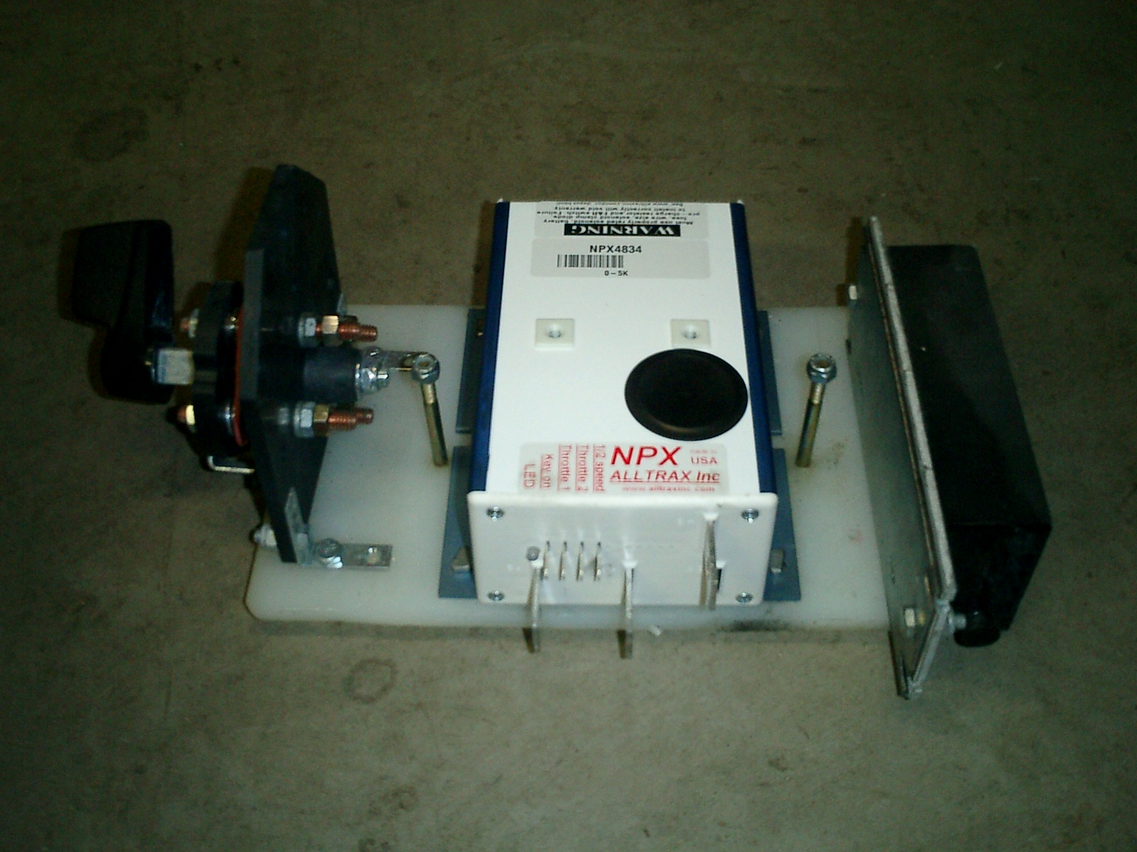
The reversing handle, speed controller and DC-DC converter are shown mounted to a cutting board using "L" brackets, ready to mount to the frame with the two bolts on either side of the speed controller. Using a cutting board not only saves time painting but it's corrosion proof too! You will notice that this DC-DC controller is an upgrade from the recommended one. This converter has a higher capacity than the basic one and is also isolated. This means it will be no problem to install a radio or some other high-power 12V accessory. Being isolated, it's much less likely to send a 48V surge through the 12V system should it fail.

Here is an image of the 48V wiring so far with the speed controller assembly lifted into place. Due to tight space, I found the lugs from the speed controller should be attached at right angles, then run under the reversing switch to come up where the battery tray is. To do this required using a Dremil tool to cut out a bit of battery tray although I also could have done so from the switch support instead. (see small square cut out on battery tray - to the left of the switch). To attach the lugs to the copper terminals on the controller and contactor, I use stainless steel nuts which I hope will resist corrosion better than the typical nut.

The wiring is also modified slightly from the plans. Two 48V wires needed to meet at a terminal in the contactor hump. However space was very tight there. So I moved the connection point for the two wires from the contactor lug bolt up the wire to the switch lug bolt. Electrically, nothing significant has changed. However, it's much easier to wire! Clicking on the image will show a larger version of the wiring diagram to show where I modified the wiring.

According to plans, the only thing holding on the motor cover is a strip of Velcro running down the trailing arm. I have found that's not sufficient since it's possible to go over a bump and lose the motor cover. So, I would recommend supplementing the velcro with a bolt as well. Just be VERY careful when drilling bolt holes for the cover. The motor has magnets in it so it's possible metal filings could be attracted to the inside of the motor causing BIG problems.
So, if the motor is already installed, before drilling, wrap the motor in plastic to prevent any metal drill filings from being drawn into the motor vents!

Tools used:
Razor knife
Dremil with cutting wheel
Adjustable wrench(s)
vice/hammer for making bolts
Bolt cutter
crimp tool
axe or large hammer (for crimp tool)

Parts used:
Wire Lugs 3/8 and 5/16 size for #4 wire $50 + shipping - ebay.
Electrical tape (3M brand)
Several lengths of #4 wire from wire spool (spool was $89+shipping)
(12) 5/16-18 Stainless steel nuts for contactor, reverse switch & custom controller bolts.
Around 6 inches of brass all thread to make bolts (since I forgot to pick up some at the hardware store)
Labor:
Around 3 hours.